

Blog 92 - My Fight with a "Traffic Light" - Details of a Loop Belt Renewal
- ranganathanblog
- Nov 20, 2022
- 14 min read

Updated: Nov 21, 2022
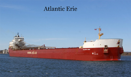
"Marine Musings 27" - "Atlantic Erie"
The critical reader will, often, find that I mix and confuse my tenses, flitting from past tense to present or future tense without breaking a sweat. It may be considered sacrilegious by some, but although I would like to humbly claim literary license for this impious use of tenses, it is just bad grammar. 'Wren and Martin' was never my favourite.
From my blog site, I find that there are two persons who are regularly reading my blog in South Korea. I request him to drop me a line at ranganathan.blog@gmail.com
Bremen Discharge and a tryst with a Sound Level Meter
The discharge at Bremen of these pellet like ore had some restrictions.
Right across the bay of our discharge berth were farms with a lot of livestock.
There had been complaints from the farmers that their livestock was being disturbed during the day and , especially, in the night, keeping them all awake - all from the noise of the running of the Self Unloader Plant while discharging the steel pellets.
A compromise had been struck between the receiving terminal and the farmers.
A sophisticated Sound Level Meter was installed in one of the fields, about a 100 metres away from the ship. The decibel level would be monitored during the day and in the nights. If beyond an agreed decibel level, the discharging was to be stopped at 6 pm, till 6 am the next morning.
The Sound Level Meter was sophisticated enough to not only measure the decibel levels, but also had light indicators of green, yellow and red, which could be seen from the ship.
The light indicator would always be in the ‘red’ range, hence it had become the norm to shut down the SUL plant every evening at 6 pm and restart the SUL plant at 6 am the next morning. The entire ship liked this arrangement wherein everybody gets rest in the nights. Quietly, everybody had fallen into this pattern and routine. Nobody tried to reduce the noise levels from the SUL.
After the first discharge, it became a professional challenge between me and the Sound Level Meter’s signal lights. Now always in the red, I wanted to see it change colours during discharge.
Having worked on several Self Unloaders before, I quickly homed in on the areas and parts that were the obvious noisemakers.
About 30 Loop Belt rollers and about a 100 boom belt rollers were renewed.
6 Pillow block bearings for main and idler pulleys - a major job - were renewed.
The teflon sheets inside the Loop Belt to Boom Belt hoppers were renewed and extra ones added to increase the thickness. The intervening areas between the Loop Belt and the Boom Belt, which had worn and damaged canvas shrouds (to prevent dust from coming out) was redesigned and covered with teflon sheets.
Over the course of the month, due to all the noise suppression work and maintenance work done, the Noise Level Meter lights had started showing yellow and then permanently green, which indicated that the noise level had abated substantially and had dropped well below the danger level.
We could now discharge cargo at night also. What used to be a 60 hour stay could now be cut down to 42.
I was roundly cursed by all on board because an easy going discharge had now become more demanding.
Instead of 3+ round trips, we could now make nearly four.
But the objection now came from the receiving terminal that they had not planned on the plant operation at night.
So, all on board had their night's rest after all.
Loop Belt Renewal :
The Loop Belt had already been damaged quite badly and was coming to a stage where the whole belt could split apart.
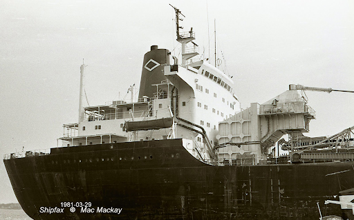
Image is representative. It shows the top portion of a Loop Bet casing, situated just forward of the accommodation. From the construction of the casing, which is the top most portion of the entire plant, one can visualise the cargo being carried from the bottom of the ship to the top, almost vertically, through the use of two loop belts, sandwiched together.
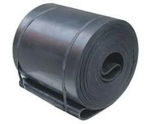
A Belt Roll - The one above is 1200 mm in width, definitely with lesser plies.
Atlantic Erie Loop Belt Width was less than 2700 mm
Bernardo Quintana was about 2600 mm outer and 2700 mm inner
Belt rubber repair kit
The rubber repair kit consists of a non-flammable polyurethane resinous compound and an accelerator. When these parts are mixed together in the proportions specified in accordance with the suppliers instructions, they form a tough flexible rubber-like compound. The two parts when mixed have a pot life of not more than ten minutes. This method of repair is for minor superficial repairs, e.g. filling rips and gouges on the surface of the belt, rubber linings etc. The rubber-like compound requires 12 to 24 hours for curing, but after two hours of application the belt can be used if necessary. The Rubber Repair Kit is available on board at all times.
Another method to repair rips and gouges on the belt is by the use of Rubber Patches, and these are of various types:
moulded rubber patch for rips and gouges, also to seal frayed belt edges
fabric re-inforced patch, used on the bottom cover for impact breaks
large rubber sheeting used with a chemical bonding layer for a quick repair of the top cover.
A “saddle” is a piece of belt of similar specification and required length, which is inserted in the damaged section of the belt by using mechanical fasteners, or by vulcanised splicing. Usable or good sections of a belt being discarded are, sometimes, retained onboard for possible use as a “saddle” or short belts.
The extra and unused lengths of newly installed belts are always kept in storage for possible renewal of sections of the belt.
Where major repairs are required on short belts such as a transfer belt, it is the preferred option to renew the belt in its entirety.
Each vessel maintains a checklist for belt repair materials and tools. It is the responsibility of the Chief Engineer to ensure that these tools and materials are maintained at the correct stock levels and that repair compounds and rubber are stored in a suitable environment to prevent decay.
Within the first month of my being on board, I tried my level best to save the costly Loop Belt by improving the condition of the damaged patches, using the belt repair kit. This is a ‘cold’ repair kit.
Within a space of two discharges, I was forced to admit to myself that it was impossible to save the belt through cold repairs. There was no alternative to renewing the loop belt.
Being quite a costly piece of equipment, a belt expert from Canada flew in to give his opinion, which concurred with mine.
A new belt was ordered and received.
Having had the experience of two belt renewals, I prepared for it by making the necessary modifications. Other preparations were made to keep everything ready for a loop belt change.
It is impossible to carry out the loop belt change without the full cooperation of the Chief Officer.
On board was a Canadian lady Chief Officer. (I only remember her name to be ‘Sophie’). At first, she kept herself away from me. After a while, seeing me always busy on the Self Unloader Plant, she started asking me how she could help and asking me to teach her the basics of the SUL.
Once the Loop Belt renewal was decided, I took her through all the steps and all the phases of the job. I was specific in what she needed to do and the safety aspects involved, so that nobody gets hurt and no accidents take place.
She turned out to be one of the best Chief Officers I have ever sailed with.
Right on top of the Loop Casing, facing forward, there is a large cover with 96 nuts, which needs to be opened to take out the belt and reeve in the new belt. Kept ready to be removed and lowered to the deck. Not very heavy.
Just inside the casing, a steel clamp (Clamp A) is to be fabricated that fits across the bottom side and topside of the entire width of the 108 inch belt. By tightening the clamp against welded large studs at both ends simultaneously, the belt is prevented from slipping down due to its weight. Two men are permanently stationed here during the entire process of removing the old belt and reeving in the new one. They are equipped with pneumatic spanners to quickly tighten the clamp, if the belt is found slipping. Kept ready.
A horizontal platform to be kept made from planks to lay out the loop belt (for which the tension is released) for the purpose of slicing the belt right across to have two ends of the belt. Kept ready.
A working platform to be fabricated for belt work outside the loop casing, at a height of about 10 metres from the deck. Kept ready.
Two strong brackets to be welded outside the loop casing (for which the working platform has been made) to hold the 7 ton new Loop Belt at a height of around 12 metres from the main deck. Brackets needed to have a half-pipe shaped receptacle, with a breaking mechanism to prevent the belt roll from moving laterally (athwartships) and a locking arrangement to prevent the belt roll from unravelling on its own. Designed and kept ready.
Wire ropes leading from the winch located between # 2 and # 3 hatches, long enough to reach the forward part of the Loop Casing. Kept ready.
A metallic clamp (Clamp B) which goes right across the width of the belt - (different from the ‘breaking’ clamp) - welded with arrangements for fitting shackles kept ready.
Wherever this wire rope was likely to chafe against any metal or any other structure, rollers were installed. Done.
Tools such as marlin spikes, various spanners, shackles, rubber belt cutting knives, gas and welding equipment, chain blocks, wire or belt ropes - all kept ready.
Several Marlin spikes, with washers tack welded to them at a particular diameter, was kept ready.
The new Loop Belt roll - about 7 tons in weight - came with a spool with extended spindles (imagine a spool with plenty of string for flying kites).
All Safety Equipment - harnesses, gloves, goggles, extinguishers, fire hoses etc - kept ready.
Sufficient manpower organised. In fact, all Tunnelmen, most of the deck crew, the Engine Fitter, Electrician, Chief Officer and Chief Engineer were all involved, with maximum manpower being required for Phase One.
The belt and vulcanising expert / technician was also with us.
1st Phase of the work involved in the Loop Belt Renewal:
This is confined to the top of the Loop Casing.
The Loop Casing front cover (the one with 96 nuts) was removed and lowered to the Main Deck, which is about 12 metres down.
A floating crane moved up to the vessel, picked up the 7 ton Loop Belt roll and lowered it on to half-pipe shaped receptacle, top cover of the receptacle (imagine a bearing cover top half) and secured, locked. Guiding this roll into place was done by ropes held by crew on main deck.
The old loop belt was now removed of its tension and placed on the wooden horizontal platform that had been kept ready.
The old belt was now cut across its width. Now the endless belt had two ends.
The next operation is something akin to reeving a new wire into a Stulken derrick, where the old wire is cut at a convenient place , the new wire attached and slowly reeved in, while the old wire is reeved out. The difference is, this is a 108 inch (2700 mm) wide, 1 ½” thick, 300 metres or so in length, rubber belt.
Next, the prepared Marlin spike is heated (red hot) and using a hand clamp, is gently hammered in to marked areas on the belt that has been cut. The red hot Marlin spike makes a neat hole wherever it is wanted in the rubber, the size of the hole as per where the tacked on washer is located on the Marlin spike.
(Best way to make a neat hole of any size in a thick rubber or teflon sheet - heat a steel rod of the expected hole diameter and gently push it into the sheet - perfect hole).
Clamp B is fitted and bolted on to the belt, using the holes made by the Marlin spike.
The long length of wire is now shackled on to this clamp and kept ready for pulling.
The other edge of the cut old belt is now aligned with the edge of the new belt. Using special clips - like large sized staples with bolts and nuts - the two edges are clamped together.
Clamp A - which is meant to act as a ‘brake’ is now loosened a bit.
Phase Two - the old belt comes out, the new belt goes in
Using the winch at #2 Hatch, a gentle pull is exerted on the long wire that is shackled on to clamp B.
The old belt starts moving out of the loop casing towards the winch, at an angle to the deck.
The heavy new roll starts rotating because of the pull and the new belt - which is stitched / clipped on to the other end of the old one is slowly reeved in.
Meanwhile the two people at Clamp A are always in readiness to apply the ‘brake’ in case of the belt roll ‘running away’ and unravelling itself without control. (In the event of this happening, it would take a lot of donkey work and more than a day to get back to status quo).
I had positioned myself on top of the Loop Casing, where I can see the new roll, see into the Loop Casing where Clamp B is fitted on to one edge of the old belt. I am also able to see the Chief Officer and her crew far away at the winch at # 2 hatch.
I am in contact with all through the radio.
After a while of pulling the old belt, due to the belt’s own (considerable) weight, it starts hanging down and spreading itself on the hatch covers.
At this time, the ‘brake’ is applied with Clamp A and also the stopper on the new belt roll., to keep everything stationary.
The old belt is then cut at a convenient place on the hatch cover, Clamp B - which, by now, would have nearly reached the winch at #2 Hatch - is removed and once again fitted on to the old belt that remains to be drawn / pulled out.
This operation of clamping - pulling belt - cutting belt - removing clamp - refitting clamp - again pulling on the old belt is repeated till the clipped on edges of the old belt and new belt is sighted. Which means that the new belt has now gone around the entire reeving area.
Keeping the fabricated ‘brake’ on, the clips are removed.
The old belt is pulled away using the winch.
Enough slack is given on the new belt going from the spool.
The belt is cut.
The spool is now separated from the rest of the new belt that has been taken into the system.
The new belt ends are then clipped on together and made very secure.
The ‘brake’ clamp (A) is released .
Phase 3 - The Clipped on belt ends brought to a convenient work space
The Loop Belt motors are switched on and slowly operated, till the clipped on joints reach the bottom of the loop.
A large flat bed work table is constructed where the ends are stretched flat on the table.
The new belt ends are now prepared for splicing together / vulcanising / ‘cooking’, in order to make it an ‘endless’ belt.
Belt hot vulcanised splice
Hot Vulcanised Splices utilise heat and pressure to form a ‘permanent bonding’ and are used in the splicing of newly installed belts to form a loop or an endless belt.
The splice is formed by stripping back the belt layers to form steps, and impregnating the layers with glue, placing the ends together and covering them with rubber.
Depending on the installed capacity of the plant, the different conveyor belts are chosen, in terms of width of belt, the thickness and the number of plies to each belt, the different belt speeds.
Proper vulcansing of the belt ends is the most important part of a belt renewal.
Loop belts are normally either 9 ply or above, making the belt more than 1.5 inches thick. Each ply is cut and stripped back in a step-like pattern at one end of the belt. A similar mirror image of the same lengths of strips are cut away at the other end of the belt. When these two cut out sections are placed one on top of the other, the steps need to match perfectly to return the belt back to its original thickness.

Representative : The cross section of a belt, showing its plies
Imagine a drawing of a series of broad steps (breadth of around 15 inches) going up. If you were to place a large mirror over these steps, a perfect mirror image will appear. Imagine this mirror image to be a drawing. Pulling them together, you will find that the steps match and align themselves perfectly, with only the slightest hint of an outline.

Representative : Stripping the belt in a step-cutting process
One edge only shown
This is what is done to the plies of the belt and then the surfaces are prepared - sand papered, washed, cleaned with special cleaners, dried and vulcanising solutions applied.
The splice area is then held under pressure by specially constructed transverse bars of a “cooker”, which has heating elements.
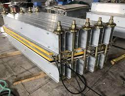
Integrated Rubber Vulcanising Machine - fondly called "The Cooker"
When using the cooker, it is essential that the correct voltage and phase are supplied, it is well grounded, and the area of usage is clean and free from dampness. All insulation must be tested.
Hot vulcanising can be carried out on any belt type, and is to be considered as a permanent repair. It is used in splicing both damaged and newly installed belts. Hot splicing carried out correctly does not appreciably reduce the belt strength. It is the best and only method to splice steel chord belts. The belt performance will be adversely affected if the splice is unsatisfactory and results in the non-linearity of the belt, (the belt ends are not aligned properly), this causing the belt ‘training’ to waver from one extreme to the other.
(Some of the above details are from Self Unloader manuals).
With the ‘cooking’ going on, the heightened activity of the past two days lessened and allowed us the comfort of sleep in rotation. The 'cooker' needs to be moved several times to 'cook' the entire joint area. The whole process lasts about 32 hours.
After allowing the vulcanising to cool for several hours, tension was slowly applied on the belt and the hydraulic tensioners adjusted. Several trial runs later, the belt technician and I were satisfied that the job had been done well.
Meanwhile, a floating crane had once again attended the vessel and removed the remaining spool of the belt from its stand and deposited it right forward, with the eventual idea of storing the remaining belt roll in the Forepeak Store. The crane was also used in lifting the front cover of the loop casing and fitting it in place.
All staging, clamps and platforms were removed prior trying out the loop belt.
Canadian Steamship Lines were really surprised to see that we had completed what was normally a 7 day job in just below a 100 hours.
The Belt expert, on his return to Canada, submitted his verbal and written reports to the CSL Office. When asked about the less number days to complete what had always been a 7 day job, he had stated in his written report and verbally that ‘it was due to the depth of preparation’ for the job. A copy of the report later came to the ship.
A message of commendation was received from the Owners.
Along with all the Self Unloader work, I was also kept busy in the Engine Room, the condition of which showed more than a year of neglect. There had been a sense of lethargy all around, so I had to wake all up with some stern words and sterner work allocation.
I was on board this ship for just under 3 months. While leaving, the Owners gave me a generous bonus for outstanding service.
With the ‘Atlantic Erie’, I bade goodbye to Self Unloaders because I felt we were being exploited by not being paid the wages commensurate with the difficulties and scope of the job, especially for a Chief Engineer. I had made it plain in all quarters on this matter. The wages paid were - at that time - a hundred dollars more than what was being paid to a Bulk Carrier Chief Engineer.
For a Chief Engineer, the ships, in order of difficulty - scope of work, quantum of work, amount of rest - are
Self Unloaders
Car Carriers, Super Carriers
Multi Purpose Carriers
Bulk Carriers
General Cargo Vessels
Since I have not sailed on tankers or gas carriers, LPGs and the like, I have no standing to comment on them.
As promised by Capt Karnick, I was signed off just short of three months.
With this, I bade goodbye to self unloaders.
The only 2 positives about them was the fact that 6 or 7 months would pass in the blink of an eye. Before you knew it, it was time to go home.
The second was the extreme self confidence that is gathered. One felt that, after working on several Self Unloaders, there is no job that you cannot tackle, no problem that you cannot resolve.
I understand that, starting from 2008, wages for Self Unloaders were increased slightly, after finding no takers for Chief Engineer posts.
===== "Atlantic Erie" Marine Musings 27 Ends ===
"Marine Musings 28" Begins in next Blog =====


Comments