

BLOG 80 - "Marine Musings 21" - "Citadel Hill" - My First Self Unloader
- ranganathanblog
- Oct 9, 2022
- 8 min read

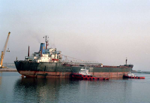
MARINE MUSINGS 21 - CITADEL HILL -
MY FIRST SELF UNLOADER - 16th Sept 1987 to 28th May 1988
Thanks to shipspotting.com
Marine Musings 21 -
Chapter 1 - How does a Self Unloader Work?
How does a self unloader work?
For a Chief Engineer, a Self Unloader is the most strenuous of ships, where he has to take responsibility of two completely different plants, both requiring different types of expertise.
The video link above merely scratches the surface of what is in store for a new Chief Engineer, the video showing only the most basic of a self unloader’s operation.
Most seafarers would not have sailed on Self Unloaders, hence I feel a brief description is necessary and in order. Since a lot of what I want to write about has been succinctly stated in “bulkcarrierguide.com”, the link being https://bulkcarrierguide.com/self-unloaders.html
I intend to only copy / paste some crucial aspects, so that a clear understanding is achieved.
Self unloading bulk carriers originated in the Great Lakes. The “Conveyor System” was installed into the Lakers size bulk carriers to deliver to ports with limited or no bulk-handling facility.
Self-unloaders can operate and discharge cargo in any accessible waterway. They do not require shore-based discharge systems or additional infrastructure. Anywhere from 0 to 70 metres from quayside, self-unloaders can discharge directly into a hopper, a barge, a quay or a warehouse or store. Self-unloaders can provide offshore transhipment operations, topping up or offloading into larger vessels.
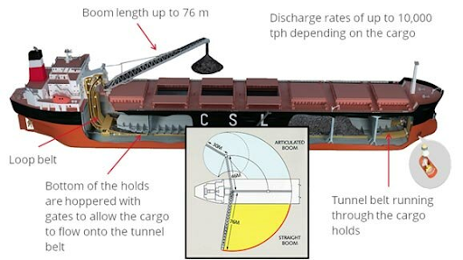
The conveyor system
The ‘Conveyor System’ is the main distinguishing feature of the vessel. An essentially industrial type conveyor system and structure, designed for shipboard use, has given a specific identity to this type of bulk carrier generally called “Self-Unloaders”. In this design the ship’s holds terminate a few metres above the DB tank top forming a series of numerous open conical shapes called ‘hoppers’. These hopper openings are capped by hinged or sluice “gates”, which are operated hydraulically.
The void space formed between the underside of these hoppers and the DB tank top along the length of the ship is called the “tunnel”. The conveyor belt runs in the tunnel along the ship’s length, and is fed by cargo through the gates. Gravity is utilised and the flow of cargo is controlled; governed by the load on the belt. The cargo is then lifted up vertically (loop or elevator lifts) or by gradual inclines and is transferred to the ship’s boom.
The boom is an extended structure with freedom of direction situated on the main deck, and encases the boom belt, for conveying the cargo to the shore terminal.
The concept of "gravity free-flow"
The “Concept of Gravity Free-Flow” is utilising the weight of the solid bulk cargoes to slide down through the gates onto the hold conveyor belt. The conveyors work as mechanical extensions, which transport the cargo horizontally and vertically. Some cargoes do not flow as well as others; and the sloping sides of the cargo holds are lined with thick Teflon or plastic sheeting, to encourage cargo flow, however on occasion certain cargoes may require to be assisted normally.
The SUL Bulk Carriers are not dependent on bulk-handling infrastructure on shore. The ship’s boom conveyor is able to discharge cargo to the shore i.e. it is the final stage in the transfer of the cargo leaving the ship and it can be positioned to discharge the cargo in most positions to a quay, to the ground, hopper, barge or other ship etc.
The SUL “Straight Boom” has freedom of movement in three directions up to the ship’s beam, and the “Articulated Boom” also aft of the beam with some modifications to the boom.
Self-Unloader technology
Many self-unloaders operate with a mix of high-tech and simple gravity. The cargo falls through controlled hydraulic gates onto conveyor belts located beneath the holds. The belts carry the cargo toward the stern of the ship where it is transferred to an elevating system and lifted toward deck level. Once there, it is released onto the discharge boom, which is slewed to either port or starboard - up to 25 metres from the side of the ship (more if so installed), and then is off-loaded to the shore, either directly onto a stockpile or into a receiving facility.

Cross section of an SUL with 2 Tunnel Belts - thanks to tsb.gc.ca
Self Unloaders came into vogue as a concept to allow bulk carriers to go into remote places, as long as the water is deep enough, to discharge cargo ashore. No shore equipment is needed, as the vessel has the required equipment to discharge the cargo. The rate of discharge depends on two factors.
The capacity of the ship’s Self Unloader Plant.
The ability of the shore facility to take away the cargo discharged, except in the case of an open pile discharge.
The ease with which the cargo ‘gravity flows’ on to the discharge gates and tunnel belts.
The main design factors and components that go into proper discharge of the cargo are
The Holds have to be designed for ease of flow of cargo to the bottom gates by means of
Well sloped hoppers, to feed either 2 or 3 tunnel belts
Sides coated or fitted with Teflon sheets so that there is no sticking of cargo
Hydraulic gates, operated either remotely or at site, to open and regulate the amount of cargo falling on to the belt.
B. Tunnel belts - either 2 or 3 endless belts, running from forward to aft, under each hold for carrying the cargo aft, towards the Transfer Belts, running on rollers, with the side rollers placed at 22 ½ degree tilt, to give a cup shaped or troughed belt, so that the cargo does not spill out.
C. Transfer Belts that transfer the cargo from Port and Starboard Belts (or if 3 tunnel belts P/S/Midship) on to the beginning of the Loop Belt.
D. Loop Belts - One endless belt picks up the cargo, then another endless belt joins in and both belts sandwich the cargo between them, carrying the cargo in an upward loop - hence the term “Loop Belt’ - where the cargo reaches about 20 to 25 metres in the vertical plane and is discharged into a hopper that feeds the Boom Belt.
A simple experiment to demonstrate this: Take a slice of bread and, with palm facing upward, place the slice on the left palm.
Next place the right palm - facing downward - on top of the slice of bread, so that the slice of bread is ‘sandwiched’ between your palms.
Keeping the palms around stomach height, trace an upward arc towards the top of your head, till you reach the same vertical plane from where you started.
Your palm has moved approximately 70 centimetres vertically upward.
The slice of bread that started its travel on your left palm is now resting on your right palm.
Hydraulic Belt tensioners ensure the ‘sandwich’ effect are routinely adjusted for different cargoes. Low tensions can result in cargo falling down when being raised vertically. High tensions can cause damage to the belts.
In a Self Unloader Plant, Loop Belts are the broadest, with 120 inch wide belts being the most common.
E. Boom Belts - Boom belt speeds are kept at the maximum of the plant’s different belts.
F. Boom - About 25 metres long. Can be raised to an 18 degree angle from the horizontal. Can be swung to 90 degrees port or starboard.
Chapter 2 - Settling in and getting to know the Plant
The handing over Chief Engineer was to stay for about 15 days to initiate me into the specifics of the Self Unloader Plant. He stayed for 1 day.
When I asked the Vessel Superintendent, Mr. Ganapathy, about it, his reply was “Don’t worry. You will be okay.”
So, in order to learn from the bottom up, I started working with the ‘Tunnelmen’ and the Electrical Officer. I learnt a fair bit in less than 2 weeks, enough to cope. Lots of important add-ons came in the next two months.
Not much was on board in terms of specific drawings or manuals of instructions. But I studied whatever was available. Working with the Tunnelmen, gate mechanisms were overhauled. Hydraulics were overhauled. Gates were repaired.
There were thousands of rollers of various sizes under the belts. Invariably, after every discharge, there would be nearly a 100 rollers that would require replacement. So, the belt had to be slackened of its tension, lifted up with a belt rope and chain block, the damaged roller removed and an overhauled one put in. A lot of time used to be spent in renewing the bearings at the end of the rollers and keeping them ready as spares. Monthly consumption of those bearings used to be between 400 to 500.
Learning on the job and simultaneously finding solutions to problems was what I tried to be good at.
To understand that there is a problem, one should be aware of what is happening.
For example, take the case of so many rollers being exchanged with overhauled ones every month. One must ask oneself the right questions.
“Why are we changing so many rollers every month?”
Answer - “Because the bearings are wearing out fast”.
Next logical question - “Why are the bearings wearing out so fast?”
Two possibilities: One because of the quality of bearings or Second because of dirt getting into the bearing.
First Action - checked spare bearings, found unknown brand being used, no name on the cardboard cover of the (supposedly) new bearing - possible “reconditioned” bearing or spurious bearing, to cut costs.
Since the entire ‘tunnel’ is in a dusty atmosphere, probability of dirt getting the bearings is high.
Second Action - Putting up a requisition for “Sealed” good quality bearings, specifying manufacturer as SKF or NTN or Koyo or FAG.
Mr Ganapathy, Senior Superintendent, who I know very well, visits ship.
Superintendent : Ranga, the costs will double. What is your justification?
Me : Overall picture - Deteriorating plant as we struggle to keep ahead of breakdowns, mostly lagging behind. Too many man hours being spent on rollers - overhauling them, renewing bearings, exchanging the rollers - mainly due to poor quality, open bearings.
100 rollers to change after every discharge.
3 discharges a month.
300 rollers = 600 bearings a month X $5 per bearing = $3000 per month - with poor quality bearings.
Add overtime costs of 4 hours / day x 4 persons x $10 per hour x 25 days = $4000.
Total = $7000
With change to new bearings, we can expect the costs to be high for about 3 months.
After 3 months, anticipate:
Max 30 rollers to exchange per discharge x 3 discharges per month x $10 per bearing x 2 bearings per roller = $1800
Overtime expected to reduce by 50% or else man hours can be used to improve other areas and reduce breakdowns and time / money lost due to being off hire, as has been happening in the past on a more than regular basis.
Superintendent : Succinctly put. I will sanction the requisitions, but you have to show me results in 3 months.
As I learnt the innards of the plant, I was able to spot areas where maintenance could be improved or speeded up.
I also explored ways to reduce or prevent damages occurring regularly at various places.
Example : Tunnel belt damage, requiring inspection and repairs after every discharge for which man hours spent was considerable.
Reason - A lot of rough cargo falling on to a speeding belt when using only one-gate discharge.
Action - Used a 2 gate discharge method, where cargo discharge is less at each gate but overall discharge rate maintained. I demonstrated to the Tunnelmen how you can keep one of the forward gates of the hold slightly open, say 30 to 40% of normal and using a second gate to maintain cargo rate-of-discharge, where it would be necessary to open the gate to about 60% of normal. That way, the impact of the cargo falling on to a fast moving belt will be less, thereby reducing wear and tear. It required only one man on one belt.
Result : Lesser damage to tunnel belts, lesser repairs to belts, leading to better belt condition, lesser breakdowns / stoppages, lesser off hires.
To reduce and prevent damage to Loop Belts, we primarily started experimenting with different tensioning parameters for different cargoes. But the damage already done to the belt was quite substantial. While we continued to maintain and carry out repairs on the Loop Belt, we also started preparing for a potential Loop Belt renewal. Not having done this job before and having no instruction manuals on the subject, I spent a lot of time figuring out how I would carry out a Loop Belt renewal in the most efficient manner, in the shortest possible time.
Using the Tunnelmen as a sounding board, I drew up a plan and kept it in readiness, anticipating that I would be informed at the last minute, at the same time training them.
===== Continued in Blog 81 =====


Comments