

BLOG 54 - "Marine Musings 14" - Problem of Cylinder Head Cracking Every 7 Months for 7 Years Solved
- ranganathanblog
- Jul 10, 2022
- 14 min read

A rejoinder : For those wishing to read any of the previous Blogs, they can click on "Marine Musings" in blue letters on the top, or "Check out our site" at bottom right.
All 54 narratives can be accessed.
Chapter 3 – Problem of Cracks on Cylinder Heads, Always in the Vicinity of Air Starting Valve Pockets - "Taronga"
There were three spare cylinder heads on board. All ships carry only one as spare. Once again, it was an indication of a recurring problem. I asked the Chief Engineer to check the Norwegian records and, sure enough, they had been changing cylinder heads every 6 to 7 months for about 7 years. I started grappling with this problem.
Meanwhile, on our voyage to Dubai, we detected another cylinder head crack and had to stop and change the head. This is normally a 4 hour job, because fittings have to be taken out of the old head and fitted on the new one. (Later, I ensured that one cylinder head was completely ready, with all fittings and mountings, so that time is not wasted.)
The cleaning of the top of the liner face (conical in this engine model) where the head sits also needs to be cleaned thoroughly or else the seating will be improper and exhaust gas will leak. The new Norwegian Captain was pressing the Norwegian Chief Engineer to hurry up, hurry up and the latter was getting nervous. We were then in open, calm, seas. That was when I had my first confrontation with him. He wanted me to put the new cylinder head without cleaning the seating face on the liner. This job takes at least 1 ½ hours, due to the accumulated carbon deposits on the liner conical top. He was upset with me because I wanted to clean the area thoroughly, so that the cylinder head to liner interface would seal well.. I specifically told him that, if not cleaned thoroughly, exhaust gas will leak.
After a while, I got fed up with his constant and continued bickering and, without completing the cleaning, put back the cylinder head, made the connections, opened fuel and water, blew through the engine and started the engine. Exhaust gas started leaking immediately from one side. I did not look at him, he did not look at me. We went to full speed and for the next four days the sound of ‘pachak – pachak’ went on. The whole Engine Room went from sparkling clean to black and grey in no time. But I held my silence.
After reaching Dubai, I quietly got others ready to work on changing the cylinder head. The passage / leakage of this exhaust gas had cut a groove on the liner and the cylinder head. I got the liner groove repaired with 'Devcon' steel putty and it held. Over the next week, we washed, cleaned and painted the Engine Room, with the Chief Engineer also cleaning for at least 6 hours a day. But we both never spoke about it.
After that, he heeded my advice on all matters.
Investigation - Why are we having Cracks on Cylinder Head
The crack on the cylinder head was always located at the very bottom of the air starting valve pocket, which was unusual. Cracks occur on various parts either due to thermal stresses, impact of an object, weakened areas due to constant or alternating stresses or metal fatigue and many other causes. Normally, on cylinder heads, cracks occur at the exhaust valve seating face or the fuel injector bore, where it is possible to have a rather large temperature gradient. Causes like manufacturing defect can be safely put away, as the vessel was already 12 years old.
https://youtu.be/moXshIDLW6Y
(Starting Air Valve #marineengine #Airvalve #startair)
It set me thinking and I was mulling over what happens in the area around the starting valve and its pocket. It was not fuel related, like the burnt exhaust valves, as there was no gouging out of metal at the starting valve pocket, which would have been the case if hot fuel oil jets were to impinge on the hot surface. The heads were all cracked, not gouged. In my mind, I slowed down the process of every action that takes place inside the combustion chamber and analysed every scenario, but could not come to any practical or logical conclusion.
My thought process then went in another direction to think about “Is there a possibility of a severe temperature gradient at some point? What were we doing wrong and when?”
The only time it gets cold (relatively) inside the combustion space is when starting air is introduced into a hot combustion space of a cylinder. But there is a moderate temperature gradient during starting times, which is during manoeuvring. I then listed all the occasions when we send air into the cylinder. One of them is when we are coming into port and, before we pick up pilot. Usually this happens about ½ an hour to an hour before we pick up pilot, when we try out the engine on astern and ahead and then proceed to pilot pick up point.
(After the induction of the International Safety Management Code - ISM Code - in the 1990s, it became mandatory to try out the Main Engine in both directions well before picking up the Pilot).
When slowing down the engine from full sea speed, the unwritten rule-of-thumb is to gradually reduce the rpm at the rate of 1 rpm a minute, in order to bring down all temperatures gradually and evenly and to give time for the ship’s momentum to reduce. After reaching ‘Full Ahead’ rpm and giving it a space of 5 minutes or so, further reductions are made step-by-step, till a ‘stop’ order is given. Even with the controls at ‘Stop’ and with no fuel going in, it takes time for the propeller shaft to stop rotating. After that only can an ‘Astern’ movement be given.
('Braking Air' can be sent into the engine if an 'astern' movement is needed urgently with the shaft rotating in the 'ahead' direction; but even here there are mitigating factors - the 'ahead' rpm should not be more than 25 to 30 rpm)
If proper protocols are followed, the cold compressed air is sent into the engine when the engine’s parts are relatively cool, in comparison to sea speed temperatures.
Then I started examining how the Norwegians followed the protocol of slowing down the engine from full sea speed to a stop and starting on ‘astern’. They did not seem to care much about programmed reduction – this was done manually on this ship – and giving the engine time to cool a bit. They were always in a hurry to stop the engine, try out the engine on ‘astern’ and ‘ahead’ and proceed to the pilot pick up point, so as to keep to their stated ETAs. It would still have been okay if, after stopping the engine, some ten or fifteen minutes were to pass before giving an ‘astern’ movement and letting in cold compressed air into the cylinder. But not even 2 minutes were given. Even the propeller shaft would not have stopped rotating, before an "Astern" movement would be given, after which it would take at least three attempts to get the Main Engine running in the "Astern" direction.
In the hurried process, they were sending in relatively ‘cold’ compressed air at Engine Room temperature (of an average of about 45 degrees C), into a hot combustion chamber which was at 280 degrees or above. Moreover, when the compressed air expands the air temperature drops still further. The point of release of this compressed air is at the mouth of the air starting valve, very closely adjacent to where the cracks were being found on the inside curvature of the cylinder head.
This was apart from the stresses caused by the braking torque needed to change the direction of a shaft turning in Ahead" direction to that of "Astern".
One may well ask "Even if the Bridge were to give telegraph orders that may be detrimental to the engine components, why do you have to follow them on an immediate basis, especially as the Engineer has the controls in his hand? Knowing that it can cause damage, the Engineer can take some time to provide the movement ordered on the Telegraph".
The answer is "If Bridge Telegraph orders are not responded to immediately, it can have disastrous results, leading to collisions, grounding and the like. The Engineer in the Engine Room is not the judge of the situation portending the ship, which is the prerogative of the Captain or the Navigating Officer who is in charge at that particular time. Barring exceptional circumstances, the Engineer below expects the Bridge Officer to use his discretion and gradually slow the Main Engine down to manoeuvering speeds, in order not to stress engine components."
I took up the matter of very quick reduction of speed with the Chief Engineer, whereon he told the other Norwegians to amend the way they were reducing speed. This was done.
We had no more cylinder head cracks.
Later ships, where the engine was on Bridge Control, had a programmed timer for speed increase as well as speed decrease, which automatically did what we had to do manually. These timer programmes could be bypassed in an emergency.
An Interesting Postscript / Fall Out to the Burn Outs of Exhaust Valves and Cracks on Cylinder Heads
It must have been 1987 or 1988, six or seven years after the solutions were found to Exhaust valve Burn Outs and Cylinder Head Cracks. By then, I had been Chief Engineer for more than 5 years.
During those years, quite a few Second Engineers had served with me and had come under my tutelage, most of whom had been slowly promoted to Chief Engineer.
Also, in those years, Barber's had a "Barber Ship Management Newsletter" published (I think) every fortnight, copies of which would be sent to all ships. The contents were mostly about office events, office bearers and some articles written by some Superintendents.
As generally known, the term "Off Hire" is used when the vessel is delayed due to its inability to carry out the conditions of the Charter Party Agreement, while it is on charter. The delay could be due to Engine stoppages, cargo delays due to cargo gear breakdowns. Since the "Off Hire" clauses are numerous, I will confine myself to only "Off Hire due to Engine related Stoppages / Breakdowns", where the ship is delayed in the course of her contracted voyage.
"Off Hire" has an economic foundation - the Ship Owner loses money for every hour that the vessel is deemed to be "Off Hire". Sometimes, exorbitant claims are made by the Charterers which the Ship Owner disputes. Costly legal arbitration or court cases follow.
Coming back to the "BSM Newsletter", one such article was an analysis of "Off Hires". A 'pie chart' showed that - after analysing data, fleet wide, over a two year period - that nearly 60% of "Off Hires" were due to Exhaust Valve / Cylinder Head related problems. 20% were because of breakdown of cranes / cargo machinery. The other 20% were attributed to various other causes.
To repeat, this was about 6 or 7 years after I had been Chief Engineer.
The "60%" struck me hard, as I did not, till then, realise that it was a fleet wise problem.
After a couple of weeks of reading this article, I wrote a rejoinder, wherein I detailed the problems I had experienced on the "Taronga".
Firstly, as detailed in Blog 53, I wrote about
"Off Hire due to Burning Out of Exhaust Valves - Some Causes, Rectification and their Prevention" detailing
Misconceptions about bad 'stelliting' being the cause.
How Fuel Injector Nozzles behave and how they can cause burn out of exhaust valves, due to uncontrolled fuel spray from worn and jagged serrations of nozzle holes. How by using a magnifying glass, one can visually see the difference between a worn, serrated nozzle hole, compared to a new nozzle.
How to anticipate an exhaust valve burn out by watching the exhaust temperatures during slowing down from full sea speed.
How to follow the trail of each new fuel nozzle, spindle and guide and also each exhaust valve spindle and seat + the co-relations that can be inferred.
Secondly, as detailed in this Blog 54, I wrote about cylinder head cracks around the air exit hole of the Air Starting Valve pocket. I gave my reasons, as detailed above, of cold compressed air entering a hot combustion chamber, due to very rapid reductions in rpm.
I sent off the article to whoever was editing the 'Newsletter'; it happened to be one of the secretaries in the Hong Kong Office.
She published it in the next edition, under "Letter from the Fleet in response to the 'Pie Chart' of Newsletter No. ----".
Within a week, I started receiving many messages on board from various Chief Engineers and Masters. (Those days, we used to get a list of all personnel of each ship).
The Chief Engineers wrote in that they were having similar problems of one or both of the above. The Exhaust Valve burn out Chief Engineers wrote in and said that they had investigated, on the basis of my article, and found it 100% correct and that they had started to take measures to prevent this.
Some of them had also gone to the Captain, showed them the article about reduction of speeds in a phased manner and asked that a procedure be followed in slowly reducing engine rpm, rule-of-thumb being one rev reduction per minute from full sea speed to 'full ahead'.
Some Captains wrote in to me - most of whom I had sailed with in some capacity or other - in a jovial manner "Bada Saab, you have opened floodgates that never existed. The moment the Chief Engineer saw your article, he was in my cabin telling me 'See, Captain, see this article that Mr AR has written. We should also follow the same pattern'. I assert my right to a scotch on your account the next time we meet, for the trouble you caused me", all more or less in the same strain.
I am happy to note that almost all of them claimed that scotch at later dates.
Three Superintendents wrote to me saying "Bada Saab, thanks for making me exceed my Spares budget for these ships. I had to necessarily supply them new fuel injector spares. Anyway, I suppose I can expect 'workshop repairs' allocation to reduce."
Chapter 5 – Other Interesting Incidents
ALL COOLERS AND HEATERS ON BOARD
In order to give sufficient quantity of air into the engine, the air coolers after the turbochargers’ must be in a clean condition. The sea water sides can be easily cleaned with a little bit of effort, as it requires opening up the end covers, physically cleaning the cooler tubes with a long brush at the end of a steel rod, washing the tubes and renewing the zinc pieces that act as sacrificial anodes.
Air side cleaning is always a problem as access to the complete set of fins in the interior is difficult. Most of the time, the vessel does not have any spare cooler and, hence, these coolers are taken ashore and cleaned whenever the vessel goes into a shipyard for dry docking. So for 5 years, the cooler is cleaned ‘in situ’ when the differential pressure of air between the outlet and inlet rises beyond whatever level you deem to be right.
Most designs of air flow is the compressed air from the turbocharger flows vertically down, turns 90 degrees, passes through the air cooler and exits into the scavenge spaces. With this L-shaped design of air flow, the air cooler air side needs to be either removed from place for a thorough cleaning or the ship's staff will have to be content with whatever can be done using a spray nozzle, compressed air and a mixture of cleaning chemical + water. This method of cleaning is partially effective, at best.
Only on 3 ships did I find a design where the air flow was in a U-shape, because of which, it allowed the the top legs of the U to be sealed off, water taken in, cleaning chemical added, steam opened to the steam coils and cleaning in situ initiated. The "Chennai Muyarchi" was one such. This type of cleaning proved to be very effective.
Another design that proved to be quite effective was when the air from the turbocharger flowed vertically down the air side of the air cooler. This allowed for a pipe with spray nozzles to be inserted above the air cooler, water and chemical sprayed continuously through a pump, drained off at the bottom to flow back to the pump.
A clean air cooler would mean abundant supply of air to the engine which, in turn, meant better combustion, more output, lesser fuel consumption, lesser exhaust temperatures and less pollution from smoke.
At full speed, a differential pressure of 80 to 120 mm of water is considered normal. Over a period of a few months, this will gradually climb to 180 / 200 mm range, wherein the staff will use a mixture of cleaning chemicals and air and passing it through a nozzle, will try to get as much of penetration through the fins as possible. But this, at best, is superficial as full penetration is impossible to achieve. So the air cooler condition starts deteriorating, at first slowly and then rapidly, causing surging of the turbocharger and other problems of combustion.

Courtesy Team BHP Google
As close a representation as possible
Note the differential pressure gauge at the bottom left
Above air cooler has its cooling water connections on the rear side and not shown in the photograph. The flow of air is from the silver grey portion – which is at the outlet of the compressor of the turbocharger – downwards through the air cooler and to the bottom section. Here the air turns 90 degrees and enters the scavenge space.

Courtesy Team – BHP – Google
Diagram to given idea of what happens in a 2 stroke Marine Engine. Note the L-shape direction of flow of air. Note the rocker arm and push rod of older engines.

Courtesy Vestas Aircoil / Google
Representative Only
Portion in red are the stack of finned areas of the air cooler through which air passes
We were lucky and had a spare air cooler on board, which is never the case on any ship. (All Norwegian ships had a spare air cooler). To clean dirty air coolers, I asked the Fitter to fabricate a tank - as done on the Trianon and Tema - in which we could lower one air cooler, with coils at the bottom with holes for air to be sent in and bubbled up. A live steam connection was also given. The cooler is lowered, water and a cleaning chemical added, steam and compressed air opened and the cleaning starts. The air cooler comes out spick and span after a 3 day cycle of cleaning. To check, one has to shine a bright light from one side of the fins – it can easily be seen passing through to the other side. Choked air coolers will not allow light to pass through.
Why was the tank designed to use compressed air to bubble up at 6 to 7 bar? Compressed air bubbling up through the water meets the fins, bursts and produces kinetic energy. The shear force developed impinges on the deposits and loosens it which then fall away or float up, easily removed.
This method of cleaning was used on all coolers and heaters. It was also used on turbine rotor blades with complete success, which normally get fouled with really hard deposits. This method of using compressed air to bubble on to a surface, cleans deposits of unburnt carbon, ash, vanadium pentoxide from vanadium content, all in the fuel and calcium carbonate from cylinder oil. Vanadium deposits are hard to clean, but they soften in the action of air bubbles, after which they can be easily brushed off.
Following this success, I tried to ensure that a cleaning tank was fabricated on most of the ships I sailed on.
We Have a Liner Crack on the Main Engine
On one of the voyages, when we were about 2 days away from Singapore, I noticed symptoms on the Main Engine that indicated either a cracked exhaust valve, a cracked cylinder head or a cracked liner - all of which show exactly the same symptoms. By isolating, we narrowed it down to a cracked liner.
Renewing a liner meant stopping the ship for about 16 hours, which I was interested in doing, as I knew what exactly needed to be done. But the Norwegian Chief Engineer was adamant that the ship's staff cannot do what he thought was a complicated job and asked for a workshop to be arranged to carry out the job in Singapore. So we cut out the unit and sailed into Singapore, with a few hours delay.
The following are some of the photographs taken during the course of the liner change.

Workshop on the Job

Workshop on the Job

Jacket Cooling Water Space with Liner Removed - Cleaning and Inspection

Crack Detecting Spray Kit Used to Detect Crack and Extent of Crack
White Layer on Left of Picture Shows Crack on Old Liner.
Note the conical shape of the liner top.

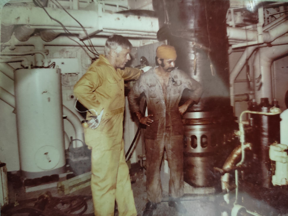
The Chief and I - Examining the New Liner

New Liner being Removed from its Stand - Weight 3 Tons Approximately
The Chief and I Watching the Cleaning
The photographs are courtesy Mr. Peter Yip, Assistant to Mr. Datta of the Singapore Office, who came on board with the workshop workers by launch to the vessel, which was then at anchor. He presented me, on the next voyage, with an album of about 20 photographs, otherwise I would never have thought of taking them.
===== To Be Continued in Blog 55 =====


Comments