

Blog 144 - PART IV - RUDDER AND STEERING
- ranganathanblog
- Nov 30, 2024
- 3 min read


RUDDER
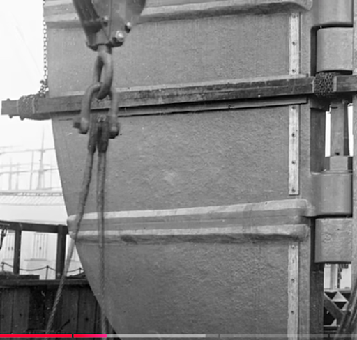

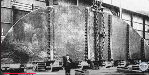
The Rudder during the Construction stage

Note the 6 pieces of solid mild steel, each bolted on to the next with 3.5 inch bolts

Red shaded portion shows the Rudder Stock

Rudder stoppers were provided to restrict the turning of the rudder to less than 40 degrees
Unbalanced rudder. 78 feet tall. 101 tons.
Turning angle restricted to a maximum of 40 degrees, to prevent overload on the rudder and to prevent the rudder from shearing off.
Present day turning angle is restricted to 35 degrees to either port or starboard.
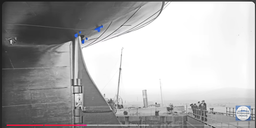
Blue shaded pad eyes were introduced for maintenance work on the propellers and rudder
Probably one of the first ships to introduce pad eyes on the ship’s stern for rigging up chain blocks / tackles for rudder and propeller maintenance. The practice continues till today.
STEERING

Older, smaller ships machinery for turning the rudder

Titanic’s Steering Gear for turning the rudder, located on C Deck
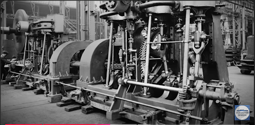
Steam Engine used for the steering gear to turn the rudder

Two Steam Engine on the shop floor, for steering gear

Massive Steering Quadrant was needed for the 101 ton rudder
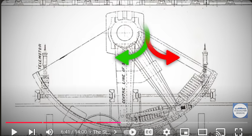
The Quadrant moves left or right depending on steering orders

Tiller Arms were used to turn the rudder, to take up the load that would have, otherwise, come on the quadrant
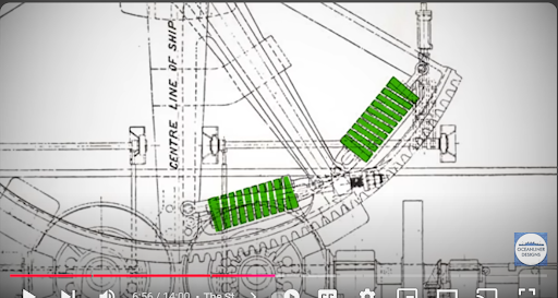
Heavy Duty Spring coils took up the shock of the turning of the heavy rudder
There were two (reversible) steam engines to give power for the steering gear, one as a ‘standby’ unit.
In an emergency, with loss of power, the ‘Tiller Arm’ (shown above in Fig ???) could be turned manually, using a block and tackle. This innovation of an emergency procedure for loss power steering is one of the concepts followed even today. Present day emergency procedures are incumbent on emergency power being supplied to one electrical motor from the Emergency Generator.
The concept of ‘back ups’ for the steering gear was, most probably, introduced for the first time during the Titanic era. This configuration of a ‘standby’ unit for steering gear is in vogue to this day.
There were three steering positions - one in a well protected wheel house, one on outside of the Bridge and one aft, directly above the steering gear. Most ships of today have one steering position inside the Wheel House (or Bridge) and an ‘Emergency Steering Position’ inside the Steering Gear Room. The steering position in the Wheel House has a ‘Follow Up’ or ‘Non Follow Up’ mode. Some ships are provided with an extension cord control, using the Non Follow Up mode that can be extended to any part of the Bridge or Bridge Wing.
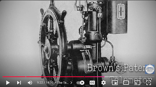
To connect the two steering positions forward to the aft of the ship, a ‘Telemotor’ was used. (It would take a while to explain the ‘Telemotor’ system, hence skipping it. Suffice it to say that turning the wheel would cause fluid in the telemotor to increase in pressure, which is transmitted to the telemotor unit in the aft steering position that controls the rudder. There was a feed back system that maintained equilibrium in the system.The Titanic used a mixture of water and glycerine as a medium to operate the telemotor. It is worthwhile noting that nearly the same design of telemotor was in use in the ships built as late as the 1960s, ‘70s and ‘80s, with solenoids in the circuit, especially for feed back. Of late, all signals are electronic, doing away with hydraulic systems and pipes.
I was surprised to learn that, of all the equipment on the Titanic’s Bridge, the Telemotor has survived the ravages of the sea and exposure for more than a hundred years.

The Telemotor, after more than a 100 years of submersion in the sea, still secured on the Bridge
AR


Comments