

Blog 143 - THE TITANIC - PART III - SHIP CONSTRUCTION
- ranganathanblog
- Nov 23, 2024
- 17 min read


THE TITANIC - PART III - SHIP CONSTRUCTION
About the Engine Room and Machinery
No. of Propellers (Total 3) - 2 x 23 feet dia, 4 bladed, outer wing propellers, moved by two directly coupled Triple Expansion Engines. 1 x 16 feet dia, 3 bladed propeller, centrally located, run by a Parson’s Turbine. (There is a dispute about the centre propeller - 3 bladed or 4 bladed?)
Single Plate Rudder mounted centrally, behind the three bladed propeller with the Low Pressure Turbine as its Prime Mover. (Single plate rudders were already being replaced by double plated hollow rudders).
No. of Boilers - 24 Double Ended, 5 Single Ended - Total 29. Huge number by any standards and any day, capable of delivering steam at 15 psi.
No. of Furnaces - 159 total - 6 per Double Ended Boiler, 3 per Single ended Boiler.
No. of coal bunkers - 6 compartments, from which coal was manually transported to the boiler furnaces. The gang that dealt with shifting of the coal were known as the ‘black gang’ and included ‘trimmers’, who ensured that the coal was removed evenly, to prevent the vessel from taking a list. They were the largest group of crew on board.
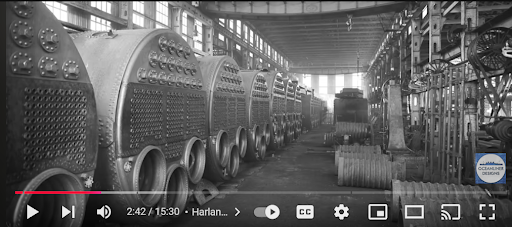
One side of the Double Ended Boilers shown here - 3 furnaces this side, 3 furnaces at the other end
Main Engines - Two - 15,000 HP Triple Expansion Reciprocating Steam Engine
And One Parson’s Low Pressure Steam Turbine Engine generating 16,000 Horse Power.
It was a unique blend, almost a hybrid system, discussed later.
The Boilers supplied steam at 215 lbs/ sq inch pressure to the two Four Cylindered Triple Expansion Engines.
After exhausting from the 4 LP cylinders of the TE Engines, the steam entered the Parson’s Turbine at 9 lbs/ sq inch, (much below atmospheric pressure {14.7 psi}) to run the Turbine.
The two Triple expansion Engines have to be working at near full speed, after which only the Parson’s Turbine can be started / coupled to run the centre propeller. This played an important part in the last few minutes before the Titanic struck the iceberg, to be taken up later.
Combined Horse Power : 2 x 15,000 + 16,000 = 46,000 HP (designed).
Looking at the configuration of 3 propellers and one rudder, I think her maneuvering capabilities at slow speeds were limited, especially when they would have had to stop the (centre) Parsons Turbine, which would have given maximum impetus to the rudder, had the turbine been running.
Without the centre turbine, how effective would the two side engines be on a centrally placed udder.
The likelihood of using one Triple expansion Engine on ‘ahead’ and the other on ‘astern’ would probably be the way they dealt with turning the ship during manouvering.
Main Electrical Power Plant - 4 x 400 kw steam driven electric generators, total output 16,000 amps at 100 V DC. (Located aft of the Turbine Enngine).
Emergency Electrical Power plant - 2 x 30 kw auxiliary generators, total output 600 amps at 100 V DC.
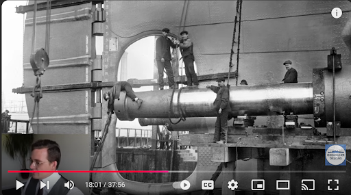
One of the interesting aspects of this photograph is the TAPER at the end of the Starboard Tail shaft (covered, with a man hanging over the edge of the shaft) - which I thought was more of a modern design / invention

Photograph of Titanic’s port Engine Lower Section in the shop
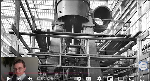
The Port Engine’s Upper side - shows the LP Cylinder
THE DESIGN AND CONSTRUCTION
The object was to build the safest of ships, the biggest of ships, not necessarily the fastest.
The Chief Designer’s drawings included some cutting edge ship construction features that were not so common in ship building but already existing in a few ships, such as water tight compartments to elevate the safety levels of the ship. This gave it the reputation of being ‘unsinkable’, a tag that would haunt it forever.
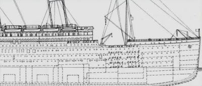
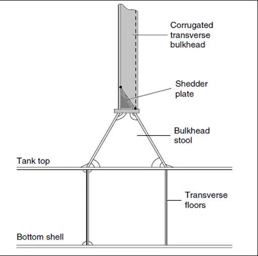
The design called for 16 watertight compartments and 15 transverse bulkheads.
The Titanic’s watertight compartments were only watertight horizontally. Also, some of them did not run in a vertical straight line.
The compartments were of varying sizes (volumes), with the Engine Room being the largest.
The critical point to note is the vertical bulkhead(s) - whether in a straight line or not - reached only the Upper Deck, which was not a Continuous Weather Deck.

Sketch showing the water Tight Bulkheads
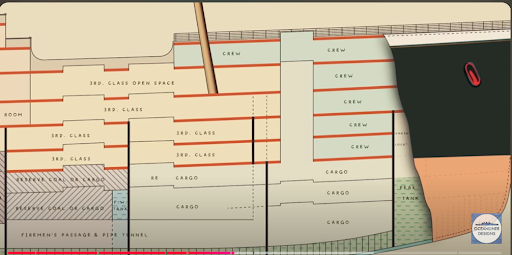
The Crucial Forward Area
The Original Drawing showing the WT Bulkheads
Had the transverse bulkhead(s) reached the uppermost continuous deck, the Titanic may have well deserved the title of ‘unsinkable’. At the worst, she would have given the survivors on board - mostly the men passengers, the Third Class passengers and crew - a few more hours, which would have made the difference between life and death. The ‘Carpathia’ and other ships would have reached the vicinity. Dawn would have come. Hope would have come.
The lower areas of each compartment was given to coal bunkers, boiler spaces, machinery spaces, engine spaces.
Above them were crew’s quarters, passenger cabins. The higher the deck, the better the class of passengers.
As a Marine Engineer, I am flabbergasted that they did not go that extra distance and say “We’ll take the transverse bulkhead right up to the top”. But I am talking from hind sight. (I have, personally, had, in an explosion forward, the experience of the forward hull being holed badly, the hull plates tearing like a piece of cloth, the Fore Peak and Lower Fore Peak store flooding, the Collision Bulkhead cracking and # 1 Hold flooding. The next transverse watertight bulkhead held. We were fully loaded and ‘down by head’ quite a bit, with water lapping the deck at # 1 and # 2 Holds, but managed to slowly reach a port for repairs. At the same time, the Australian Navy / Coast Guard were geared up to evacuate us. Except for the time when the explosion caused a massive fire - which we fought and put out in a matter of 4 hours - I do not seem to recall that I was ever worried).
One of the obvious questions are “If the transverse bulkhead is going right up to the Upper Deck, how can people or equipment move along the ship?” For this, several massive, heavy watertight doors had been provided, that could be opened and shut as needed. Most of these water tight doors were the lowering type. They could be lowered from the decks above from a remote position. They could also be raised or lowered locally.
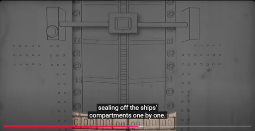
Water tight door coming down
The Watertight Door could be
Closed from a remote location
Locally
It had a float mechanism that sent the door down, if the water leve were to rise, possibly the mechanism on the right of the photograph
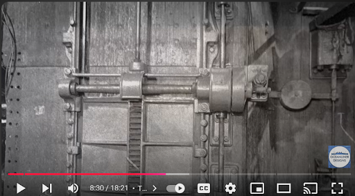
It could be opened locally by means of a pulley / handle mechanism
Another view of water tight door
But the concept of ‘water tight compartments’ - whether initially designed for the Titanic or not is a matter of debate - was, later, discussed in innumerable design offices, improved upon and, finally, reached the inevitable stage of being a continuous bulkhead right upto the continuous weather deck, making the compartment ‘watertight’ in the full sense of the word.
Present day Ships:
If it is drawn and listed as a Watertight Bulkhead, it must reach the Continuous Uppermost (Weather) Deck in the vertical plane. Horizontally, it should be from end to end. The forwardmost such Bulkhead is known as the ‘Collision Bulkhead’, thicker and stronger than the others

(From ‘Marine Insight’)
(From ‘Marine Insight’) Elevation of a corrugated bulkhead
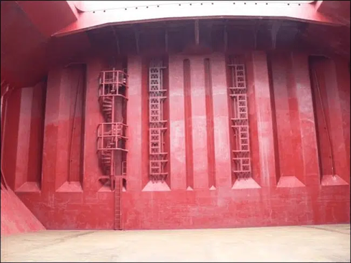
A Corrugated Watertight Bulkhead on a Modern Ship
This looks like one of the Watertight Bulkheads of a Bulk Carrier
Most Container Ships have a design wherein there are Under Deck Passages that run the full length of the ship on both, port and starboard, sides. For them to become completely watertight, heavy doors with dogs are placed at each compartment, in line with the Watertight Bulkhead. These heavy doors can be opened nad closed from both sides.
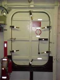
A Modern Ship’s Water Tight Door. Note the ‘Dogs’ (Cleats) that Lock the Door Down
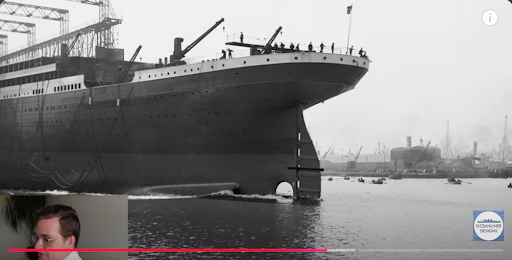
The Launching of the Ship (Stern First) (Same as today)
The Titanic Nearing Completion - her iconic four funnels in place

One of the State Rooms
SOME ASPECTS OF THE ‘SHIP CONSTRUCTION’ DETAILS OF THE ‘OLYMPIC’ CLASS OF VESSELS
Interestingly, many of the ‘Ship Construction’ features of that era still prevail in modern day ship building. Below, I will be alternating between the details of the Titanic and modern day practices as mandated by SOLAS.
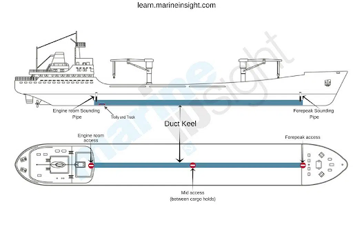
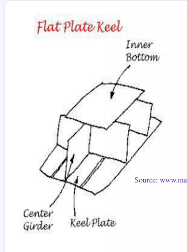
The different types of keels prevalent at that time were the Flat Keel, the Duct Keel and the Bar Keel.
Modern Duct Keel
Other Keels:
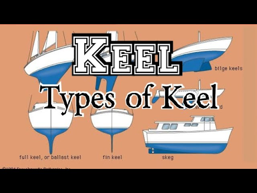
One of the famous features of H&W - almost an autograph of the shipyard - was the ‘Belfast Bottom’. Most ships were, then, designed with near - knife edge bottoms, as a pre-requisite for speed. Harland (of Harland & Wolff) came out with ships having flatter bottoms, hence the moniker of ‘Belfast Bottom’. He proved to the ship builders of that time that, even with flat bottoms, neither speed nor stability would be lost or compromised. The ‘Belfast Bottom’ was integrated with a squared off bilge. The advantage of the flat bottom was that H&W were able to increase the length of the ship, without increasing the width.
Ships of the modern era, almost without exception, have flat bottoms. The modern day ‘turn of the bilge’ at the Bilge Strake gives a near-half round shape to the ship, instead of a squarish bilge which, with welded constructions, may become a point or area of extreme stress concentration, leading to cracks.
‘Bilge Keels’ - one on either side - are a common sight in today’s world and are part of the ship’s construction in order to reduce the rolling motion. They are double riveted on to a flat steel bar that extends nearly the length of the ship. These rivets are the only ones on the hull of today’s welded ships.
It is a common sight - in dry dock - to see this Bilge Keel either bent or torn at several places, implying some type of underwater contact.
Perhaps, if the Titanic had been provided with a ‘Bilge Keel’ of a larger size, this may have ripped off when in contact with the ice berg, instead of tearing the main hull.
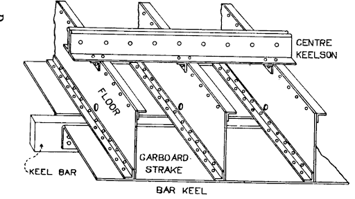
The Keel Plate was 1 ½” thick with a solid 3 ½” thick ‘Keel Bar’ that ran practically the full length of the ship. In addition, the keel was further strengthened by a 5 foot box girder, 3” thick. A surprising innovation for a ship built 115 tears ago.

Modern ships either have the ‘Keel Bar’ along with the centre longitudinal division plate (centre girder) or a ‘Duct Keel’, a box like structure to strengthen the keel area, which also becomes the space in which pipes, valves, cables are carried. A small rail / trolley arrangement is also provided to transport men and material along the length of the ship, for maintenance purposes.
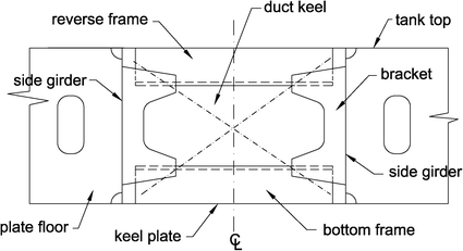
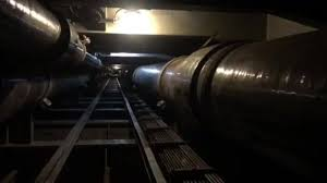
The Interior of a Duct Keel
Previously, each longitudinally placed plating had a name. The ‘Garboard Strake’ was the one either side of the ‘Keel Strake’. Then there was the ‘Bilge Strakes’, the ‘Sheer Strakes’, ‘Bottom Strakes’, ‘Lower Strakes’ etc. They have been replaced by letters for convenience.
The thickness of each strake was more the prerogative of the Designer at the time of building the Titanic.
Nowadays, a formula is used to calculate what should be the thickness of each plate and is dependent on the size of the ship, the tonnage of the ship and the draft of the ship.
I won’t go into the details of frames and their spacing or web frames and their spacing. The only comment I wish to make is that they were remarkably similar to today’s constructions.
The transverse strength was from the watertight bulkheads and girders.
The other safety feature that earned her the rather unwanted sobriquet of ‘unsinkable’ were her Double Bottoms, a concept taken for granted in today’s ship construction world, but still in its infancy in the 1900s.
The Titanic construction was a marvellous piece of engineering and ship design, most of which is followed to this day.
WROUGHT IRON USED IN THE TITANIC DAYS
Wrought iron was made by smelting pig iron and oxidising it with iron oxide in a ‘puddling’ furnace. The ease with which it could be worked into practically anything, made it very popular.
‘Puddling’ was a process of mixing and stirring molten metal in large vats where, at the same time, oxides were added to react with the carbon, manganese, phosphorous, silicon impurities and produce a more refined product, with slag being a by-product.
The quality of the product depended on the skill of the ‘puddler’ and the quality varied with each batch.
While wrought iron had many advantages, its main weakness was that it was not as strong per unit cross section as steel. In other words, where you can use a 1” steel plate to obtain a certain strength, you may have to use a 4” thick wrought iron plate to obtain the same strength as steel, making it much heavier and larger in structures, ships. (My comment - the 1” to 4” thickness is not a calculation, just an approximation, a guess)
Wrought iron came into ship building use in the 1800s. In ship building it appeared in the form of ‘Ironclads’. Wooden ships were prone to be destroyed by explosives, fire or incendiary shells, in naval battles. So, cladding the wood with thick wrought iron plates - sometimes as thick as 7 to 8” - became the benchmark of a superior navy. The progression to wrought iron ships was just a step away.
By 1860, the weaknesses of wrought iron became evident, at least as far as ship building went, so the changeover to steel took place, especially with the proliferation of Open Hearth furnaces.
One of the by products of the smelting process for wrought iron is slag, which makes the finished product brittle. The slag in the wrought iron rivets is one of the main suspects in the sinking of the Titanic. As far as the ‘Titanic’ was concerned, I’ll be exploring the impact of wrought iron rivets that were used in joining of plates.
“In the case of wrought iron from the foundries, there were huge variations. Some slag chunks were so large that cooling following the ‘puddling’ process took a very long time. As a result, coarse, tree like, structures known as ‘dendrites’ had enough time to form inside the slag. When large chunks of slag are left unrefined, they can singlehandedly control the wrought iron’s mechanical properties.
STEEL USED IN THE TITANIC DAYS
In the present day, steels are broadly divided into 4 classes : carbon steel, alloy steel, stainless steel and tool steel.
During the Titanic days, two types of steel were common : mild steel with less than 0.25% of carbon and carbon steel with carbon between 0.25% and 1.4%. Alloy steels were in their infancy, if it existed at all, in European circles. (Some Asian countries / civilisations were famous for alloy steel products more than a millenia ago).
Due to the addition of coke during the smelting process, the sulphur content in the steel plates used to be high, sometimes as high as 0.5%. Sulphur in steel can have an enhancing effect in the machinability and weldability of the steel, The process used for steel making was the Siemens Martin Open Hearth process.
The steel used on the Titanic was the same type of steel that had been used on the armed merchant cruisers, the ‘Teutonic’ and ‘Majestic; in 1889 / 1890, 20 years before. These vessels had seen service of 20 years without a doubt being cast on the quality of steel and were even then without blemish, in remarkable condition.
This kind of steel was referred to, by the dock workers, as being of ‘battleship quality.’
Plate sizes were 6 ft wide and 30 to 36 feet long. (The standard size plates of today are 6mtrs x 2 mtrs).
But at low temperatures, freezing point and below, the sulphur can cause the steel to become brittle and would easily crack.
The ‘Titanic’ was built up of thousands 1” thick steel plates. A few of the plates have been salvaged from the wreck. Dr. Phil Leighly, a Professor of Metallurgical Engineering at the University of Minnesota, Rochester, examined one or a few of them - not very clear here - and opined that the steel used in the construction did play a role in the ultimate destruction.
At the University of Minnesota Rochester, chemical and stress test of the metal samples from the hull and bulkhead show that the steel used to build the ship was incredibly inferior to modern steel. In fact, it was 10 times more brittle than modern steel when tested at freezing temperature, which was the estimated temperature of the water at the time Titanic struck the iceberg.
“Tests of the steel’s chemical composition also showed a high content of sulphur, oxygen and phosphorus. High levels of those elements cause steel to be more brittle” said Leighly in his findings.
The chemical analysis of the hull plate revealed low level of manganese, which is another symptom of brittle steel.
According to Historian Jennifer Hooper McCarty, who studied the archives of the builder, Harland and Wolff, in Belfast, Northern Ireland, shortages of steel rivets peaked during the Titanic’s construction. The Board of H&W were stressed and in crisis mode.
To build quicker, Harland and Wolff started reaching beyond their usual suppliers of rivet iron and employed smaller forges, who at that time tended to have less skill and experience.
Their ability to cut corners saw the company order No.3 bar, known as “best”, instead of No.4, known as “best-best”. Shipbuilders of that time typically used No. 4 iron for anchors, chains and rivets.
Many of the rivets recovered and studied by scientists were found to be riddled with high concentrations of slag, which is a glassy residue of smelting that can make rivets brittle and prone to fracture.
Given that the iron rivets were not as strong as steel rivets, Harland and Wolff decided to use the steel rivets only on the Titanic’s central hull, where stresses were expected to be greatest. Iron rivets were used for the stern and bow. (Wrought iron rivets)
And so, as history tells us, the bow is where the iceberg struck. Approximately six seams opened up in the ships bow plates. Scientists argue that had the rivets been better quality, Titanic might have stayed afloat long enough for rescuers to arrive, saving hundreds of lives. I will debate this later.
Some of the above data have been sourced and, sometimes, quoted verbatim from ‘ShapeCUT Steel’, a leading manufacturer of steel in Australia.
There are differing opinions on the fracture of the steel, even if it had become brittle. Some scientists say that the quality of steel was good and would have cracked only if the surrounding sea water had reached the temperature of liquid nitrogen, which would be -196 deg C (or between 63 to 72 Kelvin under atmospheric conditions).
In my opinion, the above would hold true if the steel plate does not have any impact with an object. With sulphur content being high and the sea water temperature being low (-2 deg C or below), the additional stress of impact of an object 52,000 tons weight, traveling at a speed of 22 knots - the force created by the imact would have been enormous.
Ofcourse, if the ship had only scraped the iceberg, the steel plates may not have broken. But the rivets would have been smashed, opening up the seams of the plates.
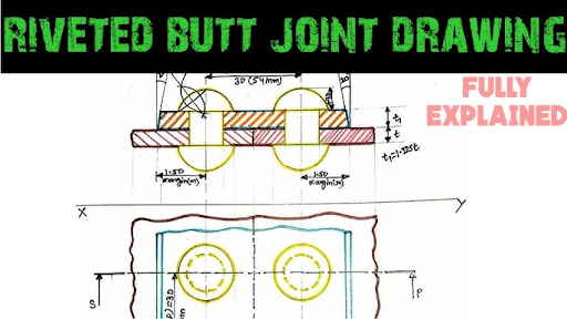
RIVETS
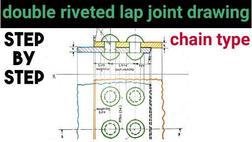
Present day ships are welded ones and have rivets at very few places.
At the time of building the Titanic, the accepted procedure for joining two plates together was to rivet them. Either the two plate edges were overlapped and riveted or the butts of two plates had a secondary plate behind the butt which was riveted. See drawing below.
Rivets of various sizes were needed. There were the hull rivets, bulkhead rivets, porthole rivets, deck rivets, boiler rivets and more.
The keel rivets were 1 ½” thick of steel or wrought iron, and had to be long enough to penetrate through 3 plates, each 1 ½” thick (total 4 ½”) or 3 plates each 1” thick.
Riveting was a laborious process. Depending on the size of the ship, literally thousands of plates - each 20 ft x 6 ft sizes - had to be riveted to make them water tight.
There were a total of between 2.5 to 3 million rivets (approximately) that were used.on the Titanic.
Inexperienced riveting personnel included 13 year old boys, who were responsible for heating the rivets in a small oven and throwing the hot rivets to the riveter, who would nimbly catch it in a bucket. Each rivet required at least 5 people - the boy heating the rivet, the riveter, one other to hammer home the rivet and two on the inside of the hull to hammer the rivet on the inside. As the Titanic completion was falling behind schedule, the pressure on the riveters became immense.
Every rivet had to heated up to exactly the right heat (distinguished by the colour of the heated rivet, rather than any other means), before being driven home. Otherwise, there could be no water tight seal between the plates.
In contrast, in the modern day, plates, frames, stiffeners are all held together by welding, whether by the human hand or by a robot.
Though the connection is not tangible, half the riveting team were unskilled workers, who were (allegedly) paid meagre wages by H&W. There were rumbles of dissatisfaction from time to time. Coud this have led to a drop in quality of riveting? This is a conjecture that has not been put to rest. (The skilled workers were well paid).
Steel rivets were used - hydraulically riveted - in the inner ⅗ th of the length of the ship. The two outer ⅕ th, the stern and the fore part had iron (read wrought iron) rivets, manually riveted.
The heavy hydraulic riveting machines were cumbersome to operate and use. Even then, they were used on the more flattened sections of the hull. The more curved sections needed to be riveted using sledge hammers.
So it came to pass that the rivets of the centre section of the hull were hydraulically riveted. The bow plate rivets were hammered home. Which is where the iceberg struck.
There were four forges contracted to deliver the 15 different types of rivets that the Titanic needed. The quality varied.
The two most used riveting methods are shown below.
One of the perplexing details that have come to light was the fact that Harland & Wolff bought rivets that had been rejected by Cunard Lines - who were building the Mauretania in 1906. H&W were leading lights in the ship building fraternity and had very high standards. So why?
The inadequacy of the Titanic period was that there was no particular standard enforced by a regulating authority in ensuring quality of steel or rivets, or even the quality of riveting.
It was only post Titanic tragedy that standards were evolved and, slowly, were set, mostly by the Board of Trade. In close resemblance to today’s reactions to a disaster by the official body, standards were revised and set after an accident, a disaster, after the results of an investigation were published.
The only tests made were that of checking with a hammer and distinguishing between the difference in the tonal quality of sound made between a rivet that was ‘home’ and a rivet that was loose. One an imagine what it would have taken to ‘hammer test’ 3 million rivets.
Sufffice it to say that riveting standards were not specifically high and there did not seem to be much of quality checks, leading to the suspicion that poor quality riveting contributed to the sinking of the Titanic.
In H&Ws favour, they had been producing ships with the same quality of steel plating, steel or wrought iron rivets for decades without any suspicion being cast on the steel or the rivets.
Again, in H&W’s favour, I can categorically state the following. If a 53,150 metric ton vessel, travelling at 22 knots (or 40 km /hr), scrapes the side of a solid, stationary object, hundreds of rivets, maybe even thousands depending on the time period of the impact, will be destroyed and pop. (F = m x a)
Even with modern day practices of welded hulls, the chances of the plates getting holed / tearing is high. The most optimistic result one can expect is the massive denting of the hull at the point of contact. There would also have been an impact force that would have pushed the hull away, after the initial collision.
Classification Society and the Titanic
To my surprise, the Titanic was not under any Classification Society, even though Lloyd’s Register, Bureau Veritas, Germinischer Lloyd and American Lloyd were very much in existence and active.
Perhaps it was felt that their - H&W and WSL - standards and design far exceeded the expertise that Lloyd’s could have brought in.
CONDITIONS IN THE YARD WHEN THE TITANIC WAS UNDER CONSTRUCTION
The ‘Titanic’ was running behind schedule. The Foremen of various departments had complained to the Supervisors that meen were slacking off and, at times, lazy.
To make matters worse, her sister ship, the ‘Olympic’ had had an accident. A naval ship HMS Hawke’s bow had collided with the stern of the ‘Olympic’, tearing two large holes in the Olympic’s, flooding two of her (supposed) water tight compartments, twisting her tail shaft and losing a propeller blade.
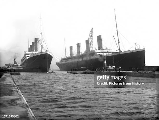
‘Titanic’ (right) moving out of dry dock to give space to the ‘Olympic’ for her collision repairs
Many workers from the Titanic had to be re-assigned to the Olympic - she was in Dry Dock at H&W - to repair her.
DELAYS TO THE DELIVERY OF THE TITANIC
The sister ship ‘Olympic’ already in service, came into the H&W Yard for major repairs, after she collided with HMS Howe, a Naval ship. Part of the Titanic workforce was re-distributed to attend to the ‘Olympic’s repairs.
A coal strike in Ireland towards the end of her completion, also delayed her.
AR


Comments