

Blog 140 - FRIDGE SYSTEMS - DETAILS - PROBLEM SOLVING - Part II
- ranganathanblog
- Oct 31, 2024
- 12 min read


Some of the more practical aspects of the ‘Fridge Plant:
A quick summary of the state of the refrigerant at each stage and trouble shooting of defects: (We start at the compressor).
Refrigerant at suction side of compressor: In cold, gaseous state. Ideal for it to be at a temperature where the suction pipe is frosting slightly.
Compressor has three gauges - showing suction pressure, discharge pressure, lubricating oil pressure.
Suction and discharge pipes have thermometers.
Compressor cuts in at a set pressure, assume 2.0 bar.
Compressor cuts out at a set pressure, assume 0.5 bar. Setting a lower pressure may induce a vacuum, in case of a malfunction.
State of the Refrigerant when leaving Compressor: Gas at high temperature and around 16 to 18 bar pressure.
Likely Problems:
Heavy fluctuations on the Suction or Discharge pressure gauges is an indication of leaky (plate) valves.
The Lub Oil pressure gauge should show Suction Pressure + about 1.2 to 1.5 bar. If suction pressure is 0.8 bar, the LO Pressure should indicate about 2.0 bar.
When overhauling the ‘fridge compressor motor, there have been incidents where the 440V cables have been wrongly connected, causing the attached LO Pump to rotate in the opposite direction, thereby not pressurising the oil sufficiently. After a while, the bearings get damaged.
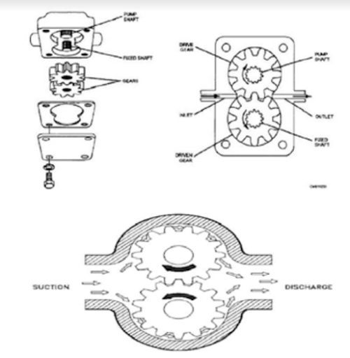
Imagine what would happen if the rotation of the Attached Lub Oil Pump is reversed
Oil Separator
Oil is not supposed to get carried over into the system.

Likely Problems:
If the Float Valve or the Solenoid valve are not working, oil will get carried into the refrigerant circuit. This will affect the cooling potential of the plant. Also, the oil combines with the bit of dirt in the system to form paste-like globules that, most of the time, stop traveling when they reach the Evaporator Coil, choking the line. Room temperatures go up.
The elements of the Separator can get dirty which, again , sends oil into the circuit.
If too much oil is being consumed by the compressor, the problem is, most likely, with the Oil Separator.
State of the Refrigerant in the Oil Separator : Gaseous, high temperature, high pressure.
Condenser / Receiver
In some systems, the Condenser and Receiver are separate units. Most of the time, they are integrated into one unit.
Sea water or Fresh Water is the cooling medium for the condenser.
Ideally, all the refrigerant should turn from hot gas to liquid refrigerant at near room temperature.
Likely Problems:
Cleanliness of the Condenser
Whichever medium (of water) is being used, the condenser tubes should be kept clean. The dirtier the tubes, the less the transfer of heat (less cooling of the gas).
As the Sea water temperature rises, so does the Discharge Pressure of the Compressor.
The reverse is also true. The Discharge Pressure of the Compressor goes down drastically with colder sea water temperatures.
It is important to maintain between 16 to 18 bar Discharge Pressure for reasons that will be explained later.
Under the circumstances of the Condenser tubes being dirty, the Receiver sight glass will show very little or no liquid refrigerant. Since the gas has not changed state because of inadequate cooling, the Receiver will be filled with gas, rather than liquid.
The state of cleanliness of the condenser can be detected by
A. Condenser / Receiver hotter to the touch than on normal days.
B. No liquid refrigerant (or very little) can be seen in the sight glass of the receiver.
C. The Discharge Pressure of the Compressor can be seen to be higher than normal.
The mistake that the staff make, at this stage, is to charge more gas into the system, thereby overcharging the system.
Wait - first clean the condenser.
Ingress of Air into the System
A. Air ingress takes place due to
1. shoddy methods of charging gas or
2. The gas in the bottle is from a dubious source and is adulterated or
3. Lots of air has entered the system during maintenance of valves or changing the silica gel of the Dryer.
B. Air in the system will show up as High Discharge Pressure of the Compressor, sometimes leading to the HP Cut Out being operated, where the compressor trips.
This can happen despite a clean Condenser.
Ideally, the amount of gas charged into the system - determined by the liquid level of the Receiver - should maintain itself from around 3/8th of the sight glass to 3/4th of the sight glass.
The fluctuation in levels takes place with more rooms being cooled at the same time or less rooms being cooled.
C. Removal of Air from the System: The air is bled out from one of the small valves provided for the purpose. All of it cannot be bled out during a single procedure. As the plant continues to be in operation, the air in the system will slowly accumulate in the Receiver. So the ‘bleeding’ operation should, desirably, take palce over a 2 to 3 day period, watching the effects on the ‘bleeding’ , the result of which can be seen by watching the Discharge Pressure gauge - the pressure will start coming down slowly.
As per (Montreal) Protocols in place, this ‘air bleeding’ must not be done straight - directly - into the atmosphere. The gases + air has to be sent into a separate, empty bottle, to be disposed off as per your Company Instructions.

Drawing of Condenser Receiver—---------------------------------
State of the Refrigerant in the Condenser / Receiver:
Enters as a gas at high temperature and pressure.
Gets colled by the coolant - either sea water or fresh water.
Exits as a liquid at high pressure (slight drop in pressure) and at near room temperature
4. Drier / Filter - To aid in removal of moisture / water particles in the system:

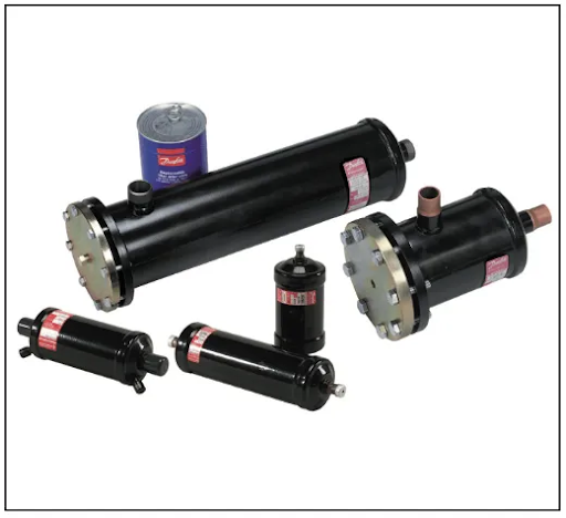
Disposable and re-usable Dryers
This Dryer contains ‘silica gel’, a desiccant - a hygroscopic substance - that absorbs the moisture in the system, but allows the refrigerant gas to pass through.
The ‘silica gel’ will change colour from crystalline white to golden brown (with less moisture, indicating it still is active) or blue (indicating it is ‘inactive’) as its full potential has been depleted.
Signs of Moisture in the System: 1. Some ships are fitted with ‘moisture indicators’. (I haven’t, personally, come across any). 2. Signs of slightly heavy to heavy frosting at the Evaporator Coils and at the suction of compressor. 3. Rooms will not cool to the set temperatures, causing the ‘Fridge Compressor to run for longer periods than normal.
Maintenance of Drier : The ‘silica gel’ is normally changed every 3 to 4 month period. The system refrigerant is taken into the Receiver and a slight vacuum is purposely interposed into the line, so that no refrigerant gas bleeds out into the atmosphere when the drier is opened.
If too much of moisture is present in the system (sometimes happens if the refrigerant bottles are supplied from a spurious source - they may have added water into the bottle to attain the specified weight) the system may need complete draining, flushing with nitrogen and refilling.
Nowadays, use-and-throw silica gel canisters are in vogue. The job of changing the silica gel is done in a matter of minutes.
State of the Refrigerant when it enters the Drier: Liquid at near room temperature, flowing at a pressure of around 16 bar. Moisture may be present.
State of the Refrigerant when it exits the Drier: Liquid at near room temperature, flowing at a pressure slightly lesser than when it entered the Drier. Leaves the Drier with lesser moisture, depending on the condition of the silica gel..
5. Liquid Line Solenoid Valve: Each room has one solenoid valve on its circuit. They are either fully open or fully closed. When the compressor runs, the coils of the solenoid valves are energised and the valves remains open and vice versa.
Problems that can occur with solenoid valves: If, due to some fault, even if one of them remains permanently open, the liquid refrigerant in the line will slowly accumulate in that particular evaporator coil, thereby reducing the liquid level in the Receiver.
At this time, the error that the operator does is to charge more refrigerant into the system.
When the liquid level in the Receiver disappears, put off the compressor and check if any of the solenoid valves are stuck open.
Once the malfunctioning solenoid valve is made operational, accumulate all the refrigerant in the Receiver and then reactivate the plant.
State of the Refrigerant at the Solenoid valve: Liquid, at room temperature and high pressure, with hardly any change between inlet and outlet of solenoid valve.
6. Expansion Valve - The most important and critical part of the entire circuit and the most sensitive.
First, identify what type of Expansion Valve is there on your ship’s Refrigerant Plant.
It can be any one of the following:
Capillary Tube
Electronic Expansion Valve (EEV)
Automatic Expansion Valve (AEV)
Thermostatic Expansion Valve (TEV) or (TXV)
The Thermostatic Expansion Valve (TEV) used to be the most common. The Electronic Expansion Valve (EEV) is replacing it in modern systems

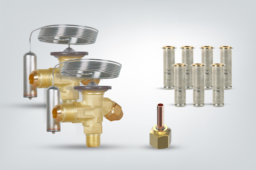
Several types of ‘Danfoss’ Thermostatic Expansion Valve Units.
Note the Capillary Tube (coiled in the picture) and the sensing bulb at the end of the capillary.

Basics of a Thermostatic Expansion Valve
Basic construction of a TEV. The flexible diaphragm actuates the poppet valve; an increasing pressure in the sensing bulb will press down on the poppet and open the valve further. There is also an adjustable spring providing a closing force on the valve which controls the superheat.

Thermostatic Expansion Valves with Different Orifices
Complex calculations have gone into deciding the size of the plant, the size of the compressor and ancillary parts, the size of the various rooms, the size of the evaporator coils, the size and type of the thermostatic expansion valve and various other parts, which is better left to the designers.
What is important is the change of state of the refrigerant that takes place in the Thermostatic Expansion Valve. This change of state sets the tone for every and all changes that take place in the entire system. All the various temperatures are maintainable because of the precise working of the Expansion Valve.
The Thermostatic Expansion Valve is a remarkable piece of engineering, as it involves several disciplines in a very small space. Several principles are involved in changing the state of the refrigerant.
Everybody knows that water is a liquid at room temperature. It turns into steam or ‘boils off’ (gaseous state) at 100 deg C.
But refrigerants, which remain as a liquid at room temperature do the reverse. They ‘boil off’ or turn into a gaseous state at temperatures below -20 deg C or much below. For example, R134a (refrigerant) is a liquid at room temperature and ‘boils off’ or turns into a gaseous state at -26 deg C.
This property of the refrigerant that reduces the surrounding temperature is what is used in refrigeration cycles.
Change of State of Refrigerant while passing through the Expansion Valve:
A. The Refrigerant reaches the Expansion Valve as a liquid at room temperature and a high pressure.
B. Changes state from liquid to partial gas and liquid while passing through the orifice - or port - of the Expansion Valve.
C. Pressure drops quite a bit.
D. The temperature drops dramatically.
E. The velocity of the refrigerant increases as it has passed through a port (an orifice). This velocity is important in ensuring that the refrigerant gas passes through the system and has enough energy left to reach the compressor suction.
Otherwise, the gas will accumulate in the Evaporator Coil and will not flow to the compressor suction.
It can be seen that, at low sea water temperatures, the discharge pressure of th compressor comes down quite a bit if the condenser sea water valves are open fully. Under these circumstances, the change / drop in pressure in the Expansion Valve is less and the gas does not have sufficient velocity to pass the evaporator coils and reach the suction of the compressor. At that time, it is necessary to throttle the outlet SW valve to increase pressure of the refrigerant - thereby the velocity - in the system.
F. Since the Expansion Valve is the most critical part of a refrigerating plant, its working should be known intimately, so that faults can be diagnosed and rectified.
G. There are three different forces at work in a TXV: bulb pressure, spring pressure, and evaporator pressure (see Figure below). Bulb pressure comes from the bulb that is mounted at the outlet of the evaporator; the bulb senses the suction temperature and drives the diaphragm down if there is an increase. Spring pressure is constant and pushes up against the diaphragm, counter to the bulb pressure. The spring pressure is calibrated when the valve is set by the equipment manufacturer or the installer. Evaporator pressure pushes the diaphragm up when the suction pressure increases and comes from the evaporator load on the system, which varies according to different operating conditions, such as room temperature changes. Based on the balance between these three pressures, the valve will either open or close. (From Danfoss website).

H. The positioning of the sensing bulb, the gentle handling of this bulb and the capillary tube that leads back to the Expansion Valve, make for efficiency in the system. Wrong placement of the sensor bulb will give a wrong signal to the Expansion Valve, due to which desired room temperatures will not be achievable. This bulb should be located on the outlet side of the Evaporator.
Although this pipe is lagged, as almost all other pipes of the system are, there should be no accumulation of ice on the pipes. Slight frosting is okay, not a thick layer of ice. This thick layer of ice will make the sensor bulb reach the wrong inputs, which will affect the precise working of the Expansion Valve. If there is ice on the pipes, put off the room for a few hours and let all the ice melt. Wipe off the droplets of water and resume cooling.
I. If the system has got oil and dirt circulating, the dirt can clog the filter of the Expansion valve. (Some Expansion valves - old type - have filters). The filter is removable and can be cleaned.
J. It is advisable not to adjust the factory settings of the Expansion Valve. You can run into a series of problems.
K. Do not pour hot water on the Expansion valve if iced up. Pouring hot water will, likely, damage the fluid in the capillary tube of the sensing bulb. Instead, allow it to melt by itself and try to find the cause of why ice has accumulated.
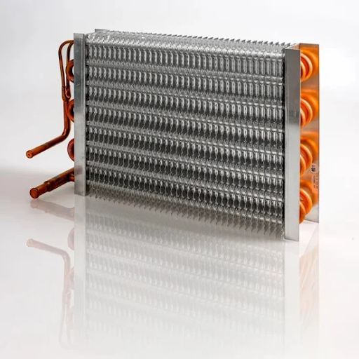
7. Evaporator Coil and Fan:

Note the gas distributor on the right. This is one of the choke points - elaborated in the text. Note the copper tubes passing through the aluminium fins.

Problems that one comes across on Evaporators:
A. Faulty fan.
B. Faulty timer (cycle) of heating coil for defrosting (de-icing) the evaporator. This allows ice to build up in the fins of the evaporator which, then, will impede the flow of air from the room into the evaporator.
C. Heavy build up of ice takes place on the evaporator due to excessive moisture in the room. This usually happens after the room doors have been kept open for long periods during bringing in supplies.
The cooling for the room should be shut off during the period of loading supplies.
This can be, usually, prevented by manually initiating an extra de-frosting cycle after the supplies have been brought in. The other option is to shut off the room cycle and allow the room temperature to go up, whereby the ice can melt. Then, after drying the water droplets in the room, the refrigeration cycle can be re-started.
If the room temperatures are constantly giving trouble, it may be that the gas is not passing through and had choked the evaporator coils at the ‘distributor’ as shown above in the photograph.
This can be caused by two anomalies.
Oil has been allowed to come in along with the gas - due to an ineffective Oil Separator or, alternatively, too much oil charged into the crankcase - and this oil has carried with it some debris and dirt in the line. After this reached the ‘U’ turns found in the cooling coils - mainly at the ‘distributor’ - the oil coagulates and freezes to form a solid block. This chokes the flow of gas.
The same problem of blockage at the same point can be caused by moisture in the refrigerant. This moisture will turn into ice in the tubes and choke the tubes at the ‘U’ turn of the copper tubes.
The only way to get rid of this is to heat the copper tubes at the bends. This will carry the oil or moisture to the compressor and needs to be got rid of, by either cleaning the oil separator or changing the drier several times.
Several times, this particular type of problem induces the Chief Engineer to requisition a brand new Evaporator, when all it requires is local heating with a blow lamp at the ‘U’ bends of the Distributor. When heated, one can hear the sound of the liquid passing, indicating the passage is clear.
D. Finding choke points along the line can be difficult, but not that difficult if one observes the system closely.
E. Maintenance of the particular room’s drain is important. The drain should not be choked by debris. Adding a little water into the drain maintains the efficacy of the ‘S’ Trap on the drain line.
8. Fault Finding in the System:
A. Most of the faults and their solutions can be found in the seven sections described above.
B. As long as the operator can, consciously, prevent oil from flowing through the system, can contain the moisture accumulated and keep away ingress of air, the system will run itself.
C. As long as wet or moist air is not allowed to enter the cold rooms, icing of the evaporator coils will not take place and the room temperatures will maintain themselves.
D. The faults that are occurring or about to occur in the system, will show up clearly as a heavy iced up section. It means there is a choke in the line before the iced section.
E. If the system is normal, the compressor will cut in, run for a while and cut out on a regular basis.
F. There is a fault if the compressor cuts in and cuts out too often, which means not enough gas is reaching the compressor in a continuous flow. Most likely accumulated in one of room’s evaporator coils. Or the system pressure is low due to low sea water temperature.
G. There is a fault if the compressor runs continuously. It means the rooms are not getting cooled, but the gas is flowing through the system. Most likely the fins of the evaporator coils are iced up. Shine a torch from one side and check for the passage of light from the other side.
H. Most of the time, if a problem occurs in a ‘Fridge Plant, arbitrary decisions are made - mostly to do with charging extra gas into the system - that may not have anything to do with the problem. A little bit of time needs to be taken to study and observe the whole plant before resorting to any work on the plant.
Happy Deepavali to all.
AR


Comments