

Blog 109 == Importance of Dew Point at Different Scavenge Pressures = The +4 Deg Method
- ranganathanblog
- Jan 18, 2023
- 8 min read


"Marine Musings 36"
(Blogs 108 and 109 are on the same subject)
The bottom bank of the air cooler now contains air that has cooled to around 60 deg C, being cooled by the colder water (assume to be 28 deg C), which has just entered the air cooler. If effective cooling has taken place, the outlet temperature of air will be around 35 deg C.
This outlet temperature can be controlled to maintain any temperature above 35 deg C, by throttling the outlet valve enough to give the desired temperature.
Water flows through the tubes and absorbs the heat from the air that surrounds the cooling tubes.
Hot, pressurised air is now flowing between the fins that surround the cooling tubes. These fins absorb the heat and transmit it to the water in the cooling tubes.
The hot and humid air at a (relatively) high pressure passes through the Air Cooler and cools to about 35 degrees C to 55 degrees C, depending on the cooling water valve settings that can regulate the temperatures. The pressure drops slightly (because of passing through a rather large seized air cooler). The velocity also drops slightly for the same reason.
The cooled air enters the scavenge space, which is constantly at around 2 bar pressure.
But the humidity in the air fluctuates wildly throughout if unregulated, being totally dependent on the air temperature achieved by the cooling water valves’ settings.
Something known as “Dew Point” becomes very important from this point on.
Two definitions of “Dew Point”:
“The temperature at which air can hold no more water vapour. Below this temperature the water comes out of the air in the form of drops.”
“The dew point is the temperature the air needs to be cooled to (at constant pressure) in order to achieve a relative humidity (RH) of 100%. At this point the air cannot hold more water in the gas form.”
What does ‘Dew Point’ have to do with scavenge air being sent into the engine?
If the temperature of air is below the ‘dew point’, there is a high possibility of a heavy concentration of water droplets, in the form of anything between micro droplets to larger sized droplets, being carried over into the Main Engine.
=======================
This air - whatever be its temperature - enters each cylinder of the engine (depending on its timing cycle) through the scavenge ports and performs two functions. It drives away the exhaust gases of the previous stroke (known as scavenging) and - as per the timing - fills the cylinder with clean, fresh, pressurised air.
With the piston moving up, the scavenge ports close and the air inside gets compressed fast. Temperatures rise quickly to 350 to 400 deg C.
Fuel is injected, combustion takes place.
Meanwhile, the engine’s cylinder liner’s outer surface - which is in contact with the fresh water being circulated - is at a temperature of between 80 deg C to 90 deg C, because of the heat being carried away by the flowing cooling water.
The engine’s cylinder liner inner surface can be anywhere between 300+ deg at the top and around 100+ deg C near the scavenge ports.
Cylinder lubrication is in full flow, the entire liner is coated again and again with cylinder oil, the motion of the piston and the piston rings spreading the oil across the surface of the liner and scraping it downwards. Cylinder lubrication is supposed to be kept at the levels suggested by the manufacturer - normally between 0.8 to 0.9 grams / bhp hr. But most Chief Engineers keep it slightly higher.
Over lubrication, in combination with moisture in the air, increases the chances of piston ring failures.
Over lubrication
With each stroke, combustion takes place.
Depending on many important factors - type of scavenging, fuel injectors’ condition, atomisation of the fuel oil issuing forth from the fuel injector, penetration of the atomised fuel into all segments of the combustion chamber, the mixing of each microdrop of fuel with the hot air, efficiency of combustion is established.
The less efficient the combustion, the more the physical debris of the remnants of combustion. The less efficient the scavenging - example ‘loop’ scavenging - the more the debris left behind.
This debris is in the form of unburnt fuel, hydrocarbons, carbon residue, other chemicals like sodium, potassium, vanadium and the like. They are in very small quantities to be sure, but each stroke brings that little bit more.
Initially, they get soaked up by the cylinder oil and get scraped down to the underpiston spaces. In the case of loop scavenged engines, they also accumulate in the scavenge ports and choke the ports, as well as get scraped down to the under piston spaces.
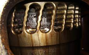
The presence of water in this scavenge air and the byproducts of combustion complicates things. The cylinder oil, the water particles and the byproducts of combustion now form a paste, which the piston rings find a little more difficult to scrape down.
This paste then starts getting accumulated gradually inside the groove of the piston, behind the piston ring.
Water + Cylinder Oil + Byproducts = Paste
The basic function of the piston ring is to seal the cylinder - seal it when compression is taking place, seal it when combustion takes place.
The piston ring also expands outwards and contracts inwards in its groove during each stroke, due to its spring action and the gas pressure behind the piston ring when the groove is clean.
If one were to calibrate an 800 mm diameter cylinder liner after 7 years or so, the top three readings will be close to 803mm. The bottom two will be close to 800.20, 800.30mm.
One can exaggerate and think of it as an inverted cone.
When the piston is at the bottom most part of the cylinder liner, the piston ring is compressed into its groove in the piston because of the lesser diameter of the cylinder liner at the bottom. If deposits have filled the ring groove behind the piston ring, the ring has no space to contract and either breaks or sticks. Maximum breakages of rings takes place at the bottom third of the cylinder line.
As the piston moves up in the cylinder liner, the diameter becomes larger and the piston ring expands to fit into this diameter.
Thus, the piston ring expands and contracts, keeping itself partially within the groove or returns back more into the piston groove.
Water + Cylinder Oil + Byproducts = Paste
This paste gradually accumulates behind the piston ring, within the piston groove.
With the heat of repeated combustion and the heat of the piston, it forms a hard crust which, in turn, prevents or reduces the in and out movement of the piston ring.
Eventually, the piston ring either gets stuck or breaks, thereby losing its function of why it was assembled there in the first place.
The more the number of stuck or broken piston rings on a piston, compression pressure reduces, combustion is compromised, hot combustion gases leak past the piston rings in what is termed a ‘blow past’, leading to scavenge fires, turbochargers surging. Worst case scenarios - piston sticks in the cylinder liner causing a twisted crankshaft - scavenge fires become uncontrollable leading to crankcase explosions.
It takes a while of continuous up and down strokes of the engine for this paste to either get scraped down or move behind the rings into the groove.
While this paste is on the liner, with the rings moving up and down over it, the effect is similar to grinding paste being used. Liner wear increases.
Many engines are prone to excessive liner wear, mostly because of the above factor. I have noted this on two different types of engines - Mitsubishi B&W and Sulzer RTA Flex engines.
Unfortunately, I did not stay long enough on the Sulzer RT Flex engine long enough to investigate thoroughly.
But I did have a measure of success on the B&W engine, using methods I have discussed below. Despite the grumbling of the Second Engineer, we pulled out two units twice within an eight month period to check liner wear and see if it had reduced. They had.
Water + Cylinder Oil + Byproducts = Paste
(A very simplified equation)
Take out the ‘Water’ component.
Send in ‘dry air’, devoid of water particles.
This is where the correct settings of the air cooler cooling water valves come in. If controlled, 95% of the water present in the air can be eliminated from entering the engine spaces. The air cooler drains should be kept clear, so that the water drains out.
The outlet temperature of the air leaving the air cooler and entering the engine should be kept at a temperature slightly above the pressure dew point (about +4 degrees C above), to ensure dry air is sent into the engine.
The pressure dew point means the temperature to which the compressed air can be cooled without condensate precipitating. The pressure dew point depends on the final compression pressure. If the pressure drops, the pressure dew point drops with it.

Example 1:
Intake air
relative atmospheric humidity j = 70 %
inlet temperature T=35°C
Example 2
Intake air
relative atmospheric humidity j = 80 %
inlet temperature T=35°C
Compressed air
Final compression pressure pop=8 bar
Þ The pressure dew point is approx. 73° C
Example 2
Intake air
relative atmospheric humidity j = 80 %
inlet temperature T=35°C
Compressed air
Final compression pressure pop=8 bar
Þ The pressure dew point is approx. 73° C
Final compression pressure pop=10 bar
Þ The pressure dew point is approx. 82° C
The instruments needed to find the pressure dew point are a wet and dry bulb thermometer (hygrometer), thermometers at various locations of the air cooler and scavenge spaces and a pressure gauge fitted on the scavenge trunking and the relevant graphs.
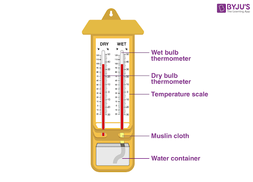
Wet and Dry Bulb Thermometer
or

Sling type psychrometer (obsolete?)

Any Number of Digital Hygrometers are Available Today

Graph 1 is on top.
Graph 2 is below.
Suppose ‘Dry Bulb’ Temperature (on the ‘Y’ axis) shows 44 degrees C (Graph 2)
Assume ‘Wet Bulb’ Temperature (as on the diagonal lines) shows 30 degrees C
Where the two lines meet, the ‘Relative Humidity’ is (approximately) 40%.
Actual Scavenge Air Pressure reads 2 Bar.
Draw a vertical (from the meeting point of 40% Relative Humidity in Graph 2) to meet the Scavenge Pressure lines in Graph 1.
A Horizontal extension to the Y axis shows 45 degrees C. This is the “Dew Point’.
Add 4 degrees more and maintain air inlet temperature at 49 ~ 50 degrees C and you are assured of dry air entering the engine.
It is often wrongly assumed that the cooler the air that is sent into the engine, all the better for the engine.
Even with cool air, the humidity is important and must be controlled.
Starting from around 1980, I have used this graph and maintained air cooler temperatures as per the graphs. On ships where I have served for longer periods, I was physically able to confirm the efficacy of maintaining the air cooler temperatures.
One of the consequences of correctly maintaining the engine inlet air slightly above dew point will be directly seen with the 'Air Coolers' Drain Tank' filling up fast.
Dew Point + 4 degrees is sufficient to drastically reduce the quantity of water entering the engine. If this air is maintained at a higher temperature than this, engine exhaust temperatures shoot up, to the detriment of the engine.
On my ships, this adjustment to the air cooler cooling water outlet valve was done at 10 am and 10 pm daily, based on the observed 'dew point'.
In the shipping world of 2023, I am certain that the graphs shown above are anachronistic and nobody will even think of using it. More sophisticated calculators are available, where you input two parameters and get a dew point at a particular pressure.
Is this line of thought in use even prevalent? I am not sure.
===== "Marine Musings 37" next in Blog 110 =====


Comments